Electrical installation:
Page 8 of 28
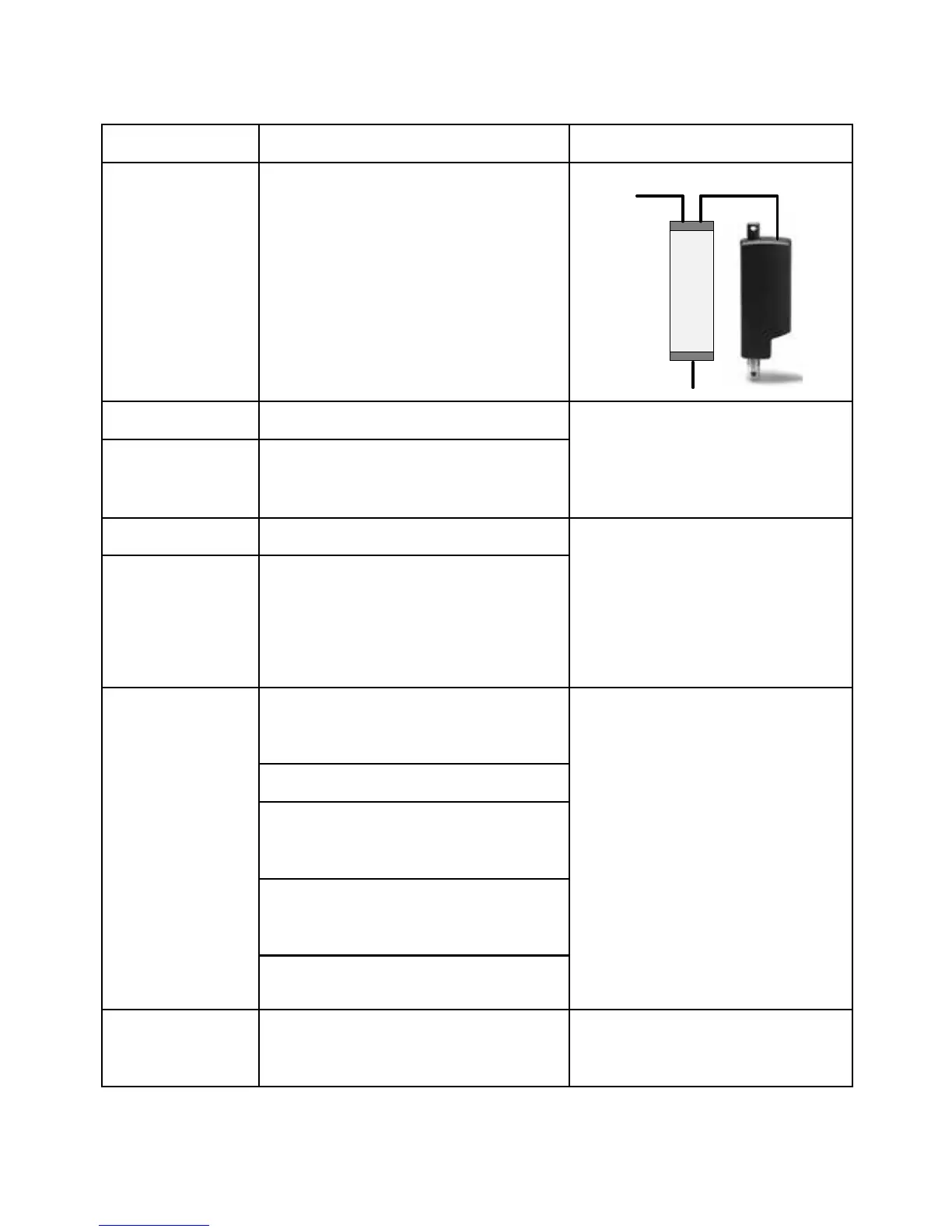
I/O specifications - SMPS with standard output interface:
Input/Output Specification Comments
Description The actuator is powered by the SMPS and
the signals are transferred to a signal cable
if attached to the SMPS
Red Extends the actuator On/off voltages:
> 67% of 29 V DC (V
IN
)
= ON
< 33% of 29 V DC (V
IN
)
= OFF
Input current: 10 mA
Black Retracts the actuator
Green Endstop signal out Output voltage min.
29 VDC (V
IN
)
- 1V
Source current max. 100 mA
Endstop signals are NOT potential free.
For further information, see the relevant
I/O specifications’ scheme in the actua-
tor’s user manual
Yellow Endstop signal in
Violet Analogue feedback (Hall Pot):
Configure any high/low combination
between 0-10V
For further information, see the rel-
evant I/O specification’s scheme in the
actuator’s user manual
Single Hall output (PNP)
Digital output feedback PWM:
Configure any high/low combination
between 0-100%
Analogue feedback (4-20 mA):
Configure any high/low combination
between 4-20 mA
All absolute value feedbacks (Hall Pot,
PWM and 4-20 mA)
White Signal GND For further information, see the rel-
evant I/O specification’s scheme in the
actuator’s user manual
Signal
Power + signal
AC supply
 Loading...