
M
Michelle ShieldsAug 16, 2025
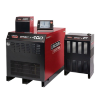
Why is there no arc at the torch of my Lincoln Electric SPIRIT II 400?
- JJermaine HallAug 16, 2025
If there is no arc at the torch of your Lincoln Electric Welding System, several factors could be responsible: * Incorrect torch consumables might be installed. Ensure you install the correct torch consumables. * Incorrect gas pressure settings may be in place. Check and adjust the gas pressure settings. * The pilot arc transistor (PAT) may not be operating correctly. Check the PAT LED (D43) on the DSP microprocessor board. * There might be damaged or loose torch lead connections. Inspect and secure these connections. * The torch or torch leads could be shorted. Check the continuity between the Electrode lead and the Nozzle lead. * The torch or torch leads could be open. Check the continuity from the Electrode lead to the torch electrode.