Left
Front Speaker
Left
Rear Speaker
+
-
+
-
Blue Wire: Power Antenna
Yellow Wire: 12 VDC Constant
Black Wire: Ground
Green Wire: Rear Left Speaker (+)
Green/Black Wire: Rear Left Speaker (-)
Right
Rear Speaker
Right
Front Speaker
+
-
+
-
White Wire: Front Left Speaker (+)
Gray/Black Wire: Front Right Speaker (-)
White/Black Wire: Front Left Speaker (-)
Gray Wire: Front Right Speaker (+)
Red Wire: Ignition Switched 12 VDC
Purple/Black Wire: Rear Right Speaker (-)
Purple Wire: Rear Right Speaker (+)
1 AMP
Audio Amplifier
See Amplifier Instructions
for Proper Connections
_
+
_
+
Brown/Black Wire
Brown Wire
White Wire
Purple/Black Wire (Common -)
Auxiliary
Speaker Left
Speaker A
Left
9-Pin
Connector
4-Pin
Connector
_
+
_
+
Gray/Black Wire
Gray Wire
Purple Wire
Auxiliary
Speaker Right
Speaker A
Right
_
+
Green/Black Wire
Green Wire
Speaker C
Left
Subwoofer
(Optional LS-SUB-75)
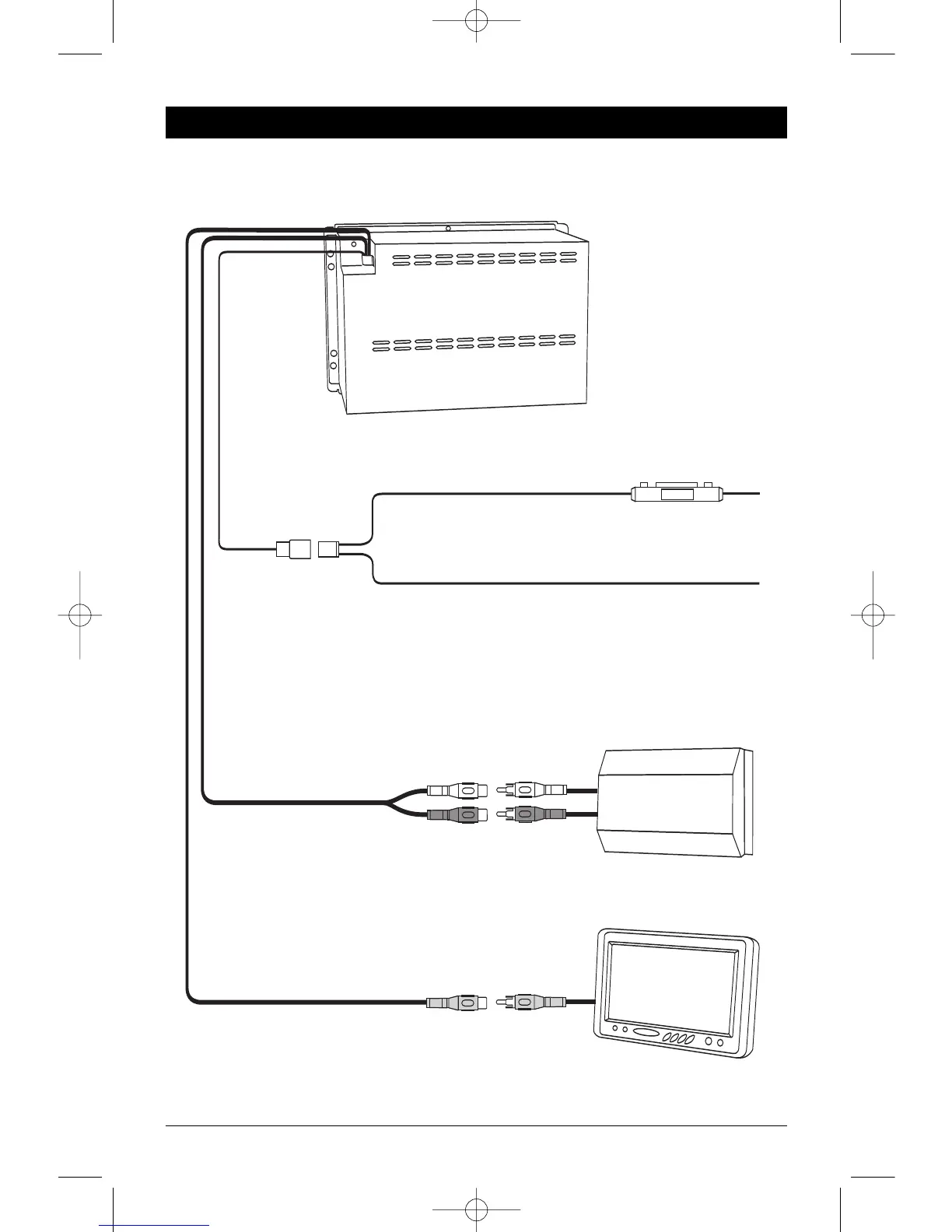
Yellow RCA
Digital Coaxial Output
Monitor
(Optional)
_
+
Blue/Black Wire
Blue Wire
Speaker C
Right
Subwoofer Output
White RCA
Red RCA
9-Pin
Connector
15A
Red Wire (+) to 12 Volt DC Power
Black Wire Ground
This unit for use only with a 12 Volt DC power source with a negative ground.
2-Channel Audio Output
White RCA
Red RCA
Amplifier
(Optional)
Video Output
Black RCA
Dolby/DTS Digital
Processor (Optional)
15A