© 2017 Linkam Scientific Instruments Ltd.
14
v1.1.0
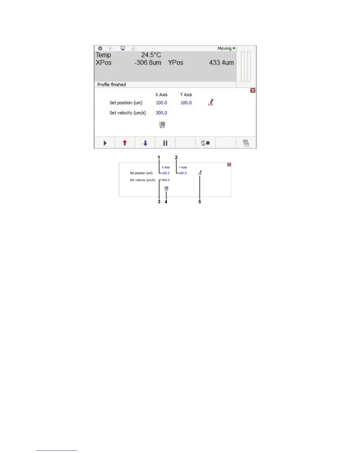
Manual motor control
These controls are us ed to move the sample ca rrier to a specific position.
1. X Axis position control
2. Y Axis position control
3. Velocity control
4. Go to zero position
5. Set zero pos ition
The X a xis (1) and Y axis (2) controls move the sample ca rrier to the position s et, which is in µm from the zero pos ition. tap on the control and a
keypad will appear where a position value can be set. ta p on the number to enter a new position and tap enter to accept and move to the new
position.
The velocity control (3) a djusts the speed at which the sample carrier will move when us ing the controls on this screen. It does not a ffect the joystick
controlled movement or the scanning movement. Speeds can be set by ta ping on the blue value a nd entering the required velocity on the resulting
keypad.
The go to zero control (4) will move the sample carrier to the currently set zero position.
The set zero control (5) will set the current position of the sample carrier as the zero point. This will cha nge the XPos and YPos values on the ma in
screen to zero without physica lly moving the sample carrier.
Note: If using a camera see the section on camera alignment in the optional LINK software ma nual and for stage alignment plea se see the ma nual
for your Linkam sta ge.
Scanning
Motoris ed stages in combina tion with the optiona l LINK software and Linkam digita l camera can 'scan' an area of your sample tha t is larger tha n the
field of vis ion. It does this by taking an image of the field of vision, moving the sample to the next field of view in the defined area and taking a nother
ima ge. Once all images are taken it will stitch the images together into one large image.
Pl ea se contact your local Linka m Dis tributor for more deta ils .
 Loading...