Page 15 of 25 FA69372–2 English
Jun 2013
25
How To Install and Set Up the 5900 &
7900 Printer
Linx 5900 & 7900
Step 4: Enter the calculated values
1 Select the shaft encoder.
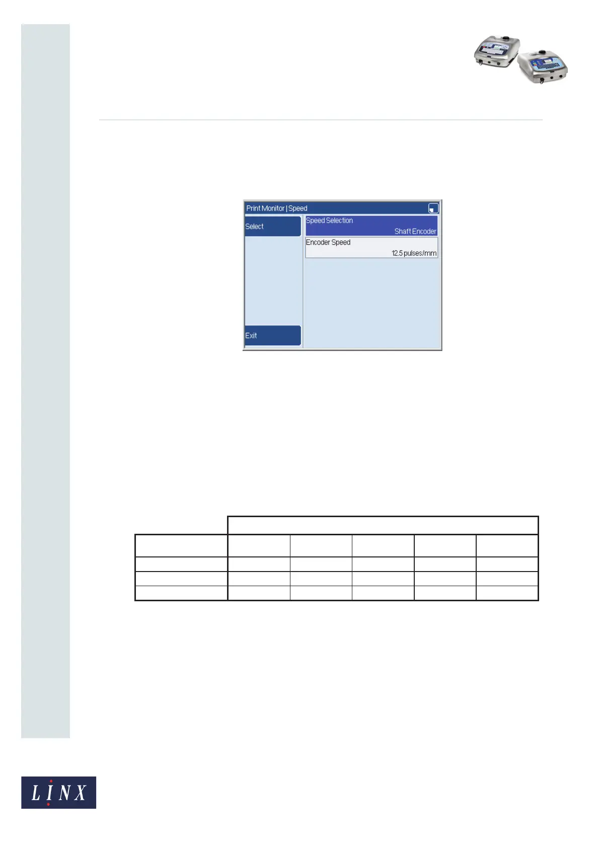
Go to the Speed page (Line Setup > Speed).
Figure 13. Speed page
Make sure that the Speed Selection parameter is set to ‘Shaft Encoder’ as shown.
2 Enter the Pulses/mm value.
At the Speed page (see Figure 13), enter the calculated Pulses/mm value into the
Encoder Speed parameter.
The Pulses/mm value is the number of pulses of the encoder output signal for every
millimetre of the product movement.
The following table shows the pulses per mm values for the combinations of Linx
standard encoders and encoder wheels.
Figure 14. Encoder pulses/mm for Linx standard encoders and wheels
3 Enter the Actual Raster Pitch (calculated from step 2).
At the Print Monitor page, press the Print Setting key to display the Print Settings
page.
Select the Print Width option and enter the calculated Actual Raster Pitch value.
The printer adjusts the value to the next lowest raster pitch given by a pitch factor,
which is a whole number. To make sure that the corrected value is accepted, and
prevent any rounding errors, enter the following raster pitch:
Selected Encoder Pitch x (Pitch Factor + 0.5)
69107
68550
Encoder Pulses per mm for Wheel Circumferences
Shaft Encoder
p.p.r.
500 mm 333 mm 304.8 mm 200 mm 50 mm
2500
5.0 7.5 8.2 12.5 50.0
5000
10.0 15.0 16.4 25.0 100.0
10000
20.0 30.0 32.8 50.0 200.0