Rev: 08.07.18 Page 7 CCD-0001772
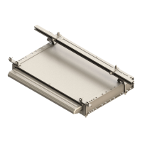
In-Wall
®
Gear Racks
Inspection
It will be important to begin with a general inspection of the gear rack to see if replacement is recommended.
Replacement
Below are the steps to replace an In-Wall® Gear Rack:
NOTE: You will notice that included in the In-Wall® Repair Package is an upper and lower gear rack section
that is longer than needed. In this case, a cut will be required to match the size of the original gear
rack.
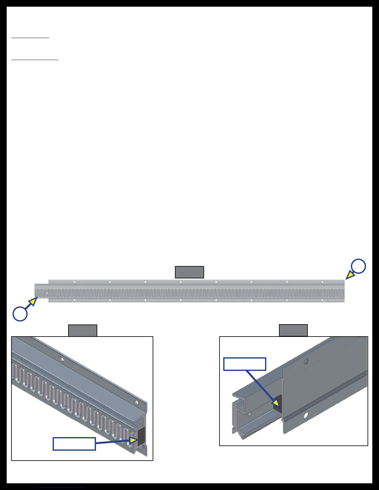
1. Measure the original gear rack, index your measurement from the “notched” end (Fig. 10A) of the gear
rack and document accordingly.
2. Transfer the measurement taken from the original gear rack onto the new gear rack.
NOTE: Remember to start your measurement from the “notched” end (Fig. 10A) of the gear rack to ensure
proper end of the gear rack is cut.
3. Check measurement prior to cutting.
4. Make the cut to the non-notched end of the rack (Fig. 10B), preferably with a chop saw to prevent
angled cut or “chewed” appearance.
5. De-burr the cut end with a fine file or emery paper.
6. Insert the corresponding foam plugs into each end of the rack to ensure that water infiltration is
prevented prior to installation (Fig. 11 and Fig. 12).
7. Gear racks can now be installed back into the columns.
NOTE: Please refer to the Re-timing Procedure section of this manual on Page 11.
8. If all other concerns have been addressed, assembly can now be installed back on the unit. See
Assembly Installation Procedure on Page 12.
Fig. 10
B
Fig. 11
Fig. 12
A
Foam Plug
Foam Plug
 Loading...