Rev: 08.07.18 Page 4 CCD-0001772
Assembly Removal Procedure
Tools Required
• Electric drill or cordless screw gun
• Rubber mallet
• 2x4 (length=gap between T-molding and side of unit-¼”)
• Razor knife
• Screw jack
Procedure
NOTE: If the slide will not move by use of the switch it may
be necessary to use one of the three methods (A, B
or C) below:
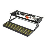
A. Use electronic override mode on the In-Wall®
controller.
I. Press the “mode button” six times quickly,
press a 7th time and hold for approximately 5
seconds (Fig. 4A).
II. The red and green LED lights will begin to flash
indicating system is in override mode (Fig. 4B).
III. Using the wall switch, press and hold the “IN”
button until the unit comes completely in.
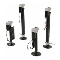
B. Disconnect the motor harnesses from the In-Wall®
controller to allow the slide room to be manually
pushed into position (Fig. 5A).
C. Disengage the motors to allow the slide room to be
manually pushed into position (Fig. 5B).
1. Remove first 3 sets of screws in each rack on the interior
side of slide room.
2. Extend the slide room until about 8" of the room is left
inside the unit.
3. Support the slide room with a screw jack or other
adequate support before continuing.
4. Place the 2x4 block on top of the slide room (standing
on its edge between the T-Molding and side of the unit.)
5. Reach inside the top of the slide column to disconnect
the wiring harness from the motor.
6. Using a razor knife, carefully cut the caulk bead along
the edge of the slide column.
7. Remove the plastic screw cover to access the mounting
screws for the clamp strap. Remove the clamp strap.
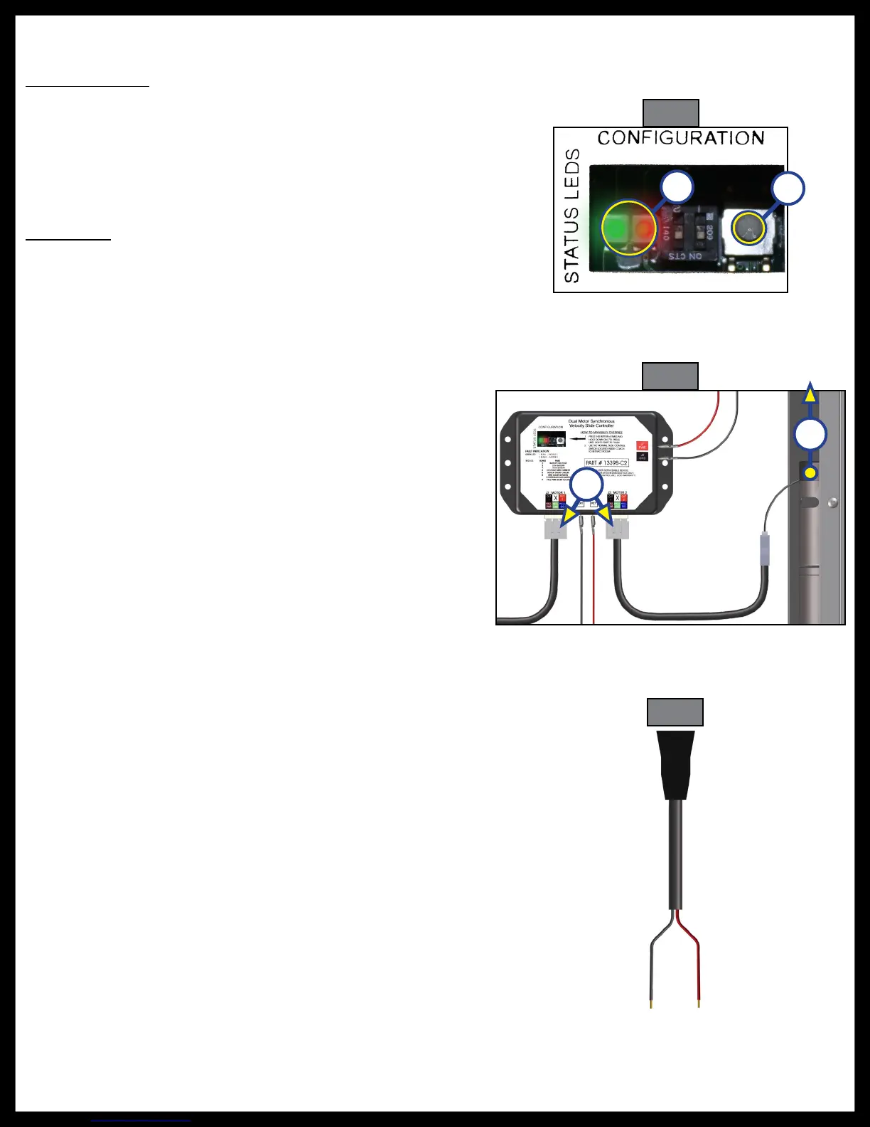
8. Create a jumper wire from an extra wiring harness: cut
a 3-foot length of the harness (with the motor wire
connector attached) and strip the ends of the red and
black wires (Fig. 6).
9. Plug the jumper wire into the motor wire.
10. Holding the black and red wires against the terminals
of your cordless screw gun battery, determine which
polarity actuates the motor in the retract direction. The
slide column should slide away from the side of the unit.
Fig. 4
Fig. 5
A
B
Fig. 6
A
B
 Loading...