8
lci1.com 574 - 537- 8900 Rev: 03.16.18
Solera
®
Power Awning
Installation and Owner’s Manual
(For Aftermarket Application)
CCD-0001261
Installation With Speakers Option
1. Remove the wire covers in both mount arms.
2. At both support arm assemblies there will be a wire
labeled “speakers.” Connect these to the radio wires
provided from the unit (Fig.11).
NOTE: Speaker wire is indicated with a blue insulation on
the wiring.
Fig.11
NOTE: On the drive side, the speaker wire will be
connected at the same location on the support arm
assembly as the power wire for the motor. On the idler
side, the speaker wire may be connected at the top or
bottom of the support arm assembly.
Fig.12
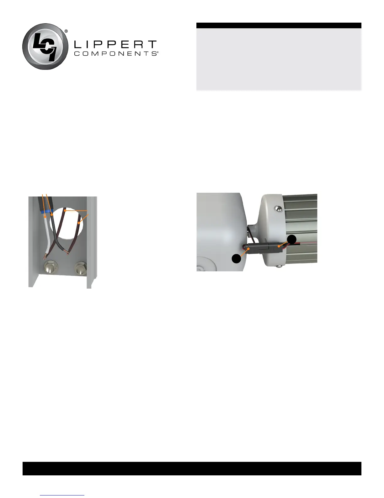
Installation With LED Options
LED Roll Tube Installation
1. Remove the wire covers in the idler side mount arm.
2. Make sure to align LED light wires (Fig.12A) coming
from the idler head with the LED light on
the roll tube (Fig.12B).
3. Connect the plug from the idler head (Fig.12A) to the
plug from the LED light (Fig.12B) on the roll tube.
4. Take the LED power wire that is already fed through
the idler leg and connect to the desired power wire
from the unit.
NOTE: Make sure the black wire is connected to a ground
wire and the red wire is connected to a 3A maximum fuse
(usually behind the switch) and then to a power source
from the unit.
speaker
wires
radio
wires
A
B