15
The power cable is terminated in round,
3 conductor connectors on both ends.
The printer end plugs into the socket
labeled ‘24VDC” on the back of the
printer and the socket labeled “Printer
Power” on the front of the supervisory
console.
Avoid placing undue stress on the cable
connectors. (i.e. avoid tight bends,
make sure that the cable is properly
supported independently from the
connector.)
The Sockets labeled “KD” (telephone
style connector) and “FG” on the back of
the printer are NOT used.
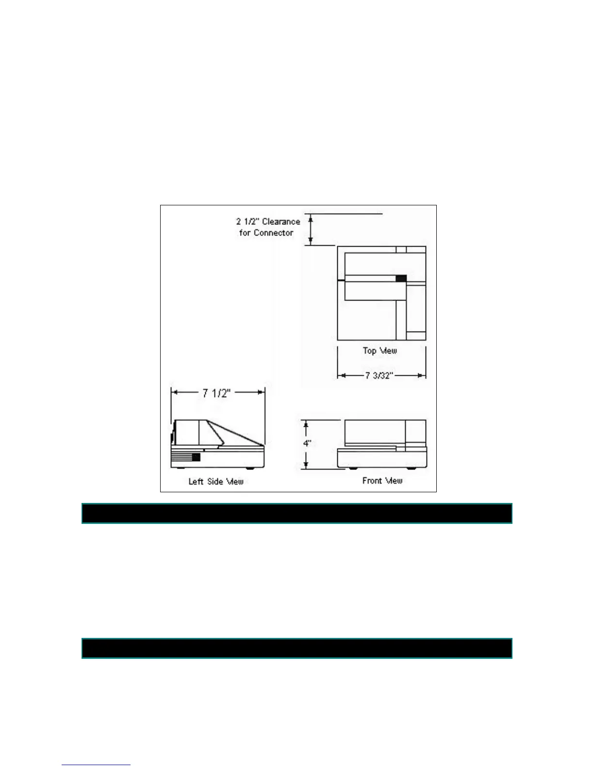
E-4900-1 Printer Dimensional Drawing
9. Removal of Mechanical Registration Equipment
Remove the existing mechanical
register components (if present) by
removing the four bolts that attach the
register “stack” to the meter and lifting
the stack off of the meter.
If you are retrofitting to Neptune Meters,
remove all of the mechanical
components from the meter, leaving just
the star shaped gear and two square-
headed studs.
If the system is equipped with a
mechanical temperature volume
compensation system, remove all of the
mechanical TVC components.
10. Install Electronic Temperature Volume Compensator
Nine different ETVC kits are available for use with the LectroCount
3
System. Nine of the
kits are designed for installation on common strainers. One is for use on systems where
a strainer cover is not available, or when physical constraints prevent its installation.