133
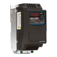
100%
Input of multi-
function analog input
terminal A1
0
( 4mA )
10 V
( 20mA )
Stall Prevention
level during run
30%
3 V
( 8.8mA )
Figure 6.82 Using Analog Input to Change Stall Prevention Level during Run
P3-07 to P3-10 Retain
P4 Frequency Detection
P4 parameters set the frequency agree and frequency detection to the assigned multi-function
output terminal.
P4-00 / P4-01 Frequency Detection Level / Width
P4-00 sets the detection level for the multi-function output terminal assigned to E2-□□ = 2
(Frequency Agree), E2-□□=3 (User-Defined Frequency Agree), E2-□□=16 (Frequency Detection
1) or E2-□□=17 (Frequency Detection 2).
P4-01 Sets the detection width for the multi-function output terminal.
Frequency Detection Level
Frequency Detection Width
<1> The upper limit is determined by the values set to d1-02 (Maximum Output Frequency), d1-13 (Motor 2
Maximum Output Frequency)and L2-00 (Frequency Command Upper Limit).
P4-02 Frequency Command Loss Detection Selection
The drive can detection a frequency command loss from terminal A1 or A2. When the
frequency command falls below 90% of the command within the time set in P4-04, the
frequency command loss will be detected.
 Loading...