47
+V
AC Drive
A1
Main frequency gain
AC
-V
Analog input common
-10V,20mA power supply
10V,20mA power supply
0 to 20mA or
4 to 20mA
V I
Dip Switch A2
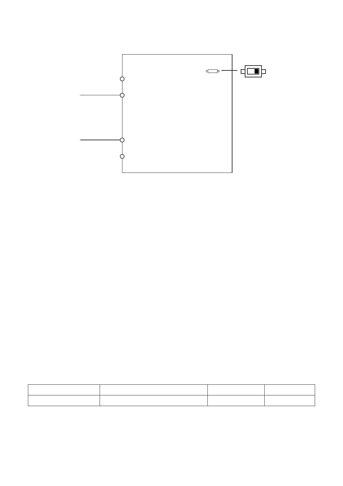
Figure 6.2 Setting Frequency Command as a Current Signal at Terminal A2
Ensure DIP switch A1 is place d to I (current).
□ Switching between Main /Auxiliary Frequency Command
If analog input terminal A1 is set to 3 ( Auxiliary Frequency Command), the multi-speed step
1 will follow analog input frequency command, for more detail please refer to table 6.12
“Multi-Step Speed Command and Multi-Function Terminal Combinations”
2 : Terminal UP/DOWN
Use digital input terminals S1 to S6 to increase or decrease the frequency.
3 : Modbus Communication
Allows frequency command via the Modbus communication. Make sure RS-485/422 serial
communications port is connected to RJ45. For more details please refer to Chap.11
b1- 01 Run Command Selection 1
Selects the run command source for the REMOTE mode.
0 : Keypad
Allows the run command via the RUN key on the keypad.
 Loading...