Page 14 Chapter 2: Introduction
The Controller Address Dial Switch sets the address of the controller module of a given stack.
It is possible to have up to 15 stacks connected in parallel and controlled by one Master
Controller.
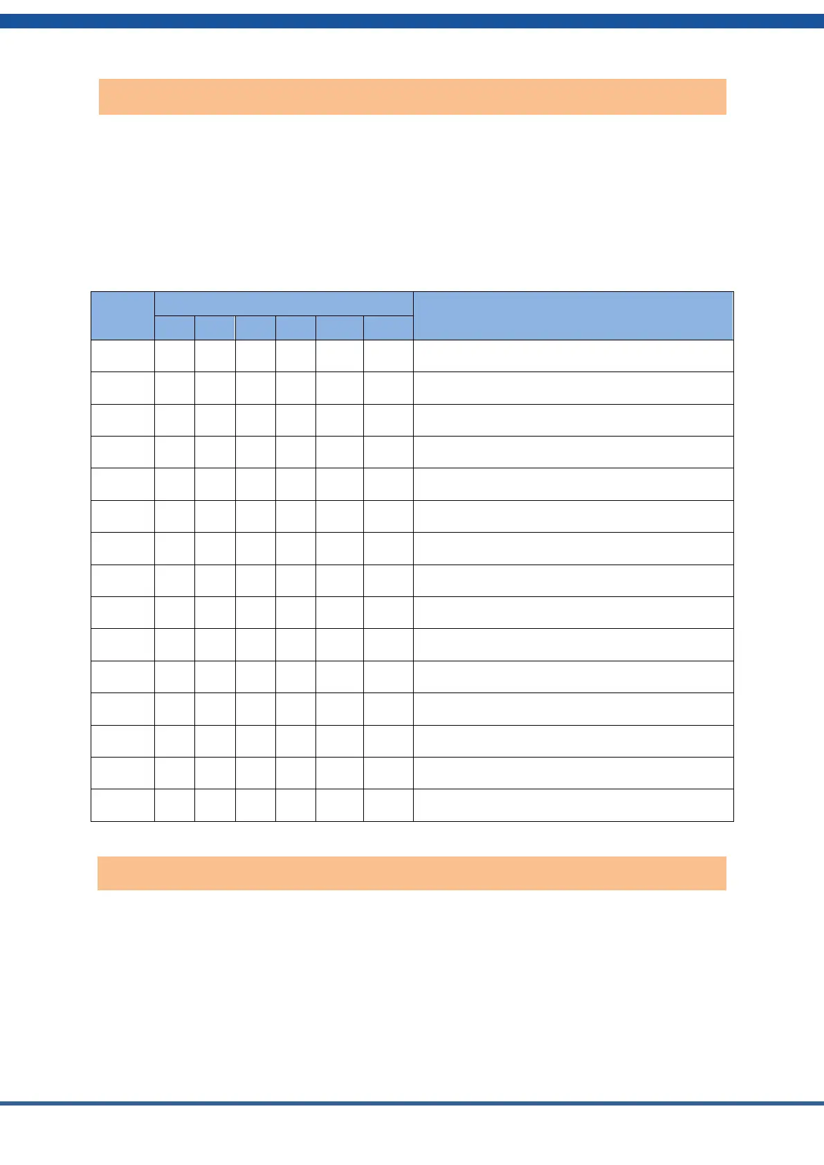
The Master Controller should have its address set to 1 as shown in the table below. The slave
controllers should be set to address 2, then 3 and so on. The controllers will be connected by
CAN bus cables shown later. Each stack has its own controller module on top.
Dial Code Switch Position
Address 1, the Master Controller
Address 2, the first slave controller
Address 3, the second slave controller
Address 4, the third slave controller
Address 5, the fourth slave stack controller
Address 6, the fifth slave controller
Address 7, the sixth slave controller
Address 8, the seventh slave controller
Address 9, the eighth slave controller
Address 10, the ninth slave controller
Address 11, the tenth slave controller
Address 12, the eleventh slave controller
Address 13, the twelfth slave controller
Address 14, the thirteenth slave controller
Address 15, the fourteenth slave controller
The master controller communicates with the inverter to set proper parameters for charging and
discharging. HomeGrid has programmed the controller to work with different inverters from
several different manufacturers.
Set the Inverter Protocol Selection Switch to match the inverter you wish to use according to
the table below.
Controller address dial switch
Inverter protocol dialing switch