Page 19 Chapter 2: Introduction
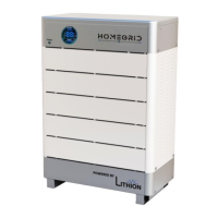
Link A / B communication port:(RJ45 port) the definition of link A and B on the rear panel of
the interface main control module is the same. This RS485 interface is used for parallel
communication between the main control modules, and up to 15 devices can be connected in
parallel.
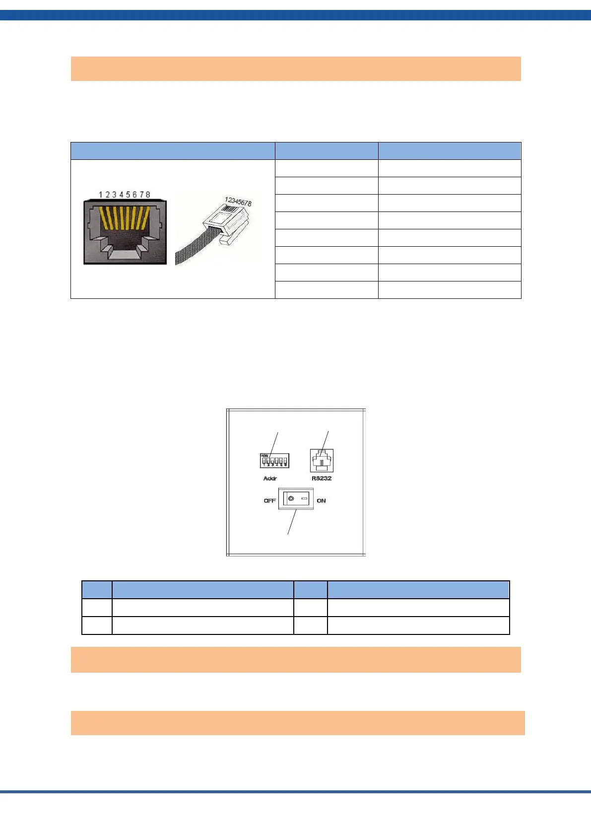
1.1. Battery Module Controls
This panel is under the cover on the right side of each battery module. The “Addr” switches
define the address of this module. Each module in a stack must have its own address. The
module directly below the controller should be set to 1, the one below it set to 2, and so on
down the stack.
Figure 2.4. Battery module interface definition
RS232 communications interface
Power switch: turns the battery module on and off.
RS232 communication port: (RJ11 port) with a baud rate of 9600 bps for debugging or service.
Rear panel Link A / Link B communication port