Gocator Line Profile Sensors: User Manual
How Gocator Works • 56
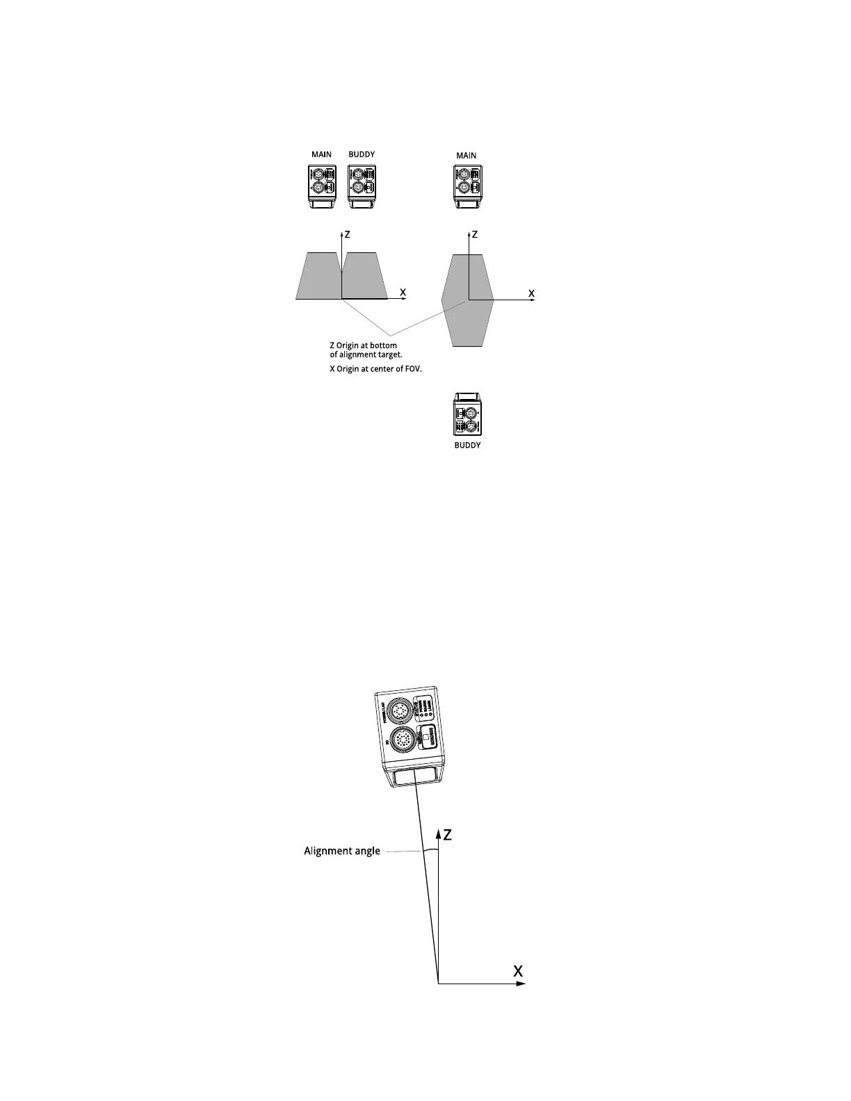
System coordinates are aligned so that the system X axis is parallel to the alignment target surface. The
system Z origin is set to the base of the alignment target object.
In both cases, alignment determines the offsets in X and Z.
Offsets can also be determined along the Yaxis. This allows setting up a staggered layout in multi-sensor
systems. This is especially useful in side-by-side mounting scenarios, as it provides full coverage for
models such as Gocator 2410 and Gocator 2420.
As with sensor coordinates, Y position increases as the object moves forward (increasing encoder
position). Gocator defines the travel direction to be forward when the object travels from the laser’s end
to the camera end of the sensor.
Alignment also determines the Y Angle (angle on the X–Z plane, around the Yaxis) needed to align sensor
data. This is also sometimes called roll correction.
 Loading...