START UP MANUAL 11
QUICK LOAD SERVO S2
4. MECHANICAL SETTINGS AND OPTIONAL ACCESSORIES
4.1 Feeding pusher
Three feeding pushers are necessary to cover the entire range of the Quick Load Servo S2
bar feed system. Each pusher has a range of operation :
Pusher diameter
Ordering Nr
Diameter Range
**6,35 mm (1/4") *021.011.022 / 6 6 mm - 12 mm (1/4" - 1/2")
12 mm (1/2") *021.011.022 / 12 8 mm - 32 mm (>1/3" - 1 1/4")
25 mm (1") *021.011.022 / 25 33 mm - 120 mm (>1 1/4" - 4,7")
* This ordering number corresponds to the complete pusher, with all of the elements
indicated below. When a feeding pusher is ordered for the first time, use this
number.
** 2 extra roller supports, intended to bolster the support of the bars of small
diameter, are furnished with the 6.35 mm diameter pushers. Their placement on
the loading table will be determined by the length of the bars to be loaded.
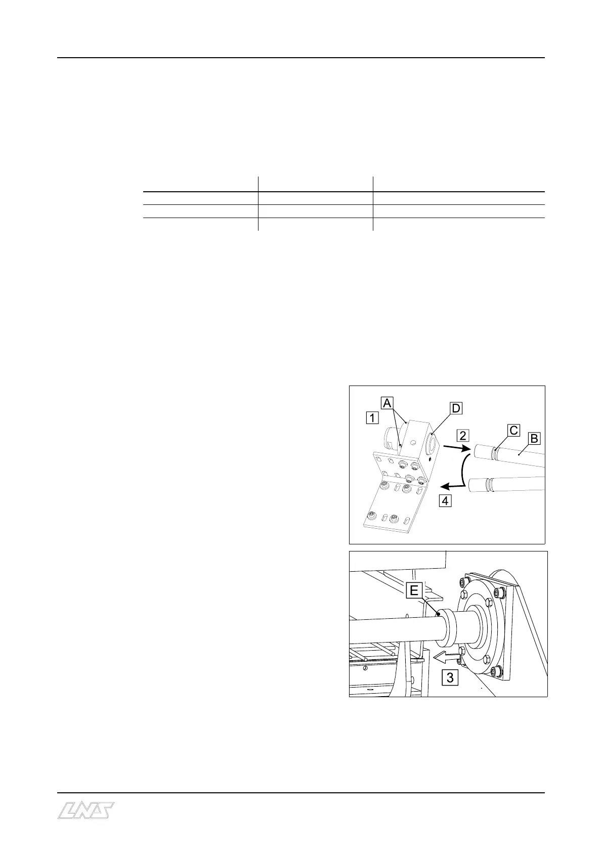
Replacement :
Bring the loading channel into working
mode position (down position), then place
the bar feed system into the STOP mode
(remote station).
1. Loosen the fastening screws (A)
sufficiently to free the groove (C) that
holds the pusher (B) in the connecting
piece (D).
2. Slide the pusher forward by
making into the guide bushing (E).
3. When the rear of the pusher is sufficiently
loosened to be able to remove it, pull the
guide bushing (E) toward the back to
dislodge it.
4. The pusher is now free and can be
removed.
• Place the new pusher into the
opening, and insert the guide
bushing.
• Introduce the rear of the pusher
into the connection piece and push
to a stop.
• Tighten the fastening screws so
that they lodge into the groove of
the pusher.
• Check to see the mechanical stop sleeve is properly positioned (see next section)