16
4 Adjustments
4. Set the control box POWER switch to the ON position
to apply 24 VAC power to the control valve actuator (pins
1 (G0) and 2 (G)). Ensure the valve is in the AUTO
position, the LED indicator will light green continuously
indicating that valve operation is normal (no faults).
5. Using a pin or paper clip, depress the AUTO-STROKE
button in the opening of the terminal housing (FIG. 4-3).
This will initiate calibration of the control valve.
6. During actuator calibration, the LED indicator (FIG. 4-3)
will flash green for approximately 10 seconds. The
control valve will be briefly closed and fully opened.
7. Upon successful completion of the valve calibration
process, the LED indicator will stop flashing and remain
ON continuously green.
8. The two-color (red/green) indicator is useful in
determining the operating status of the control valve.
Reference Table 4A for descriptions of the possible LED
status displays which may be encountered.
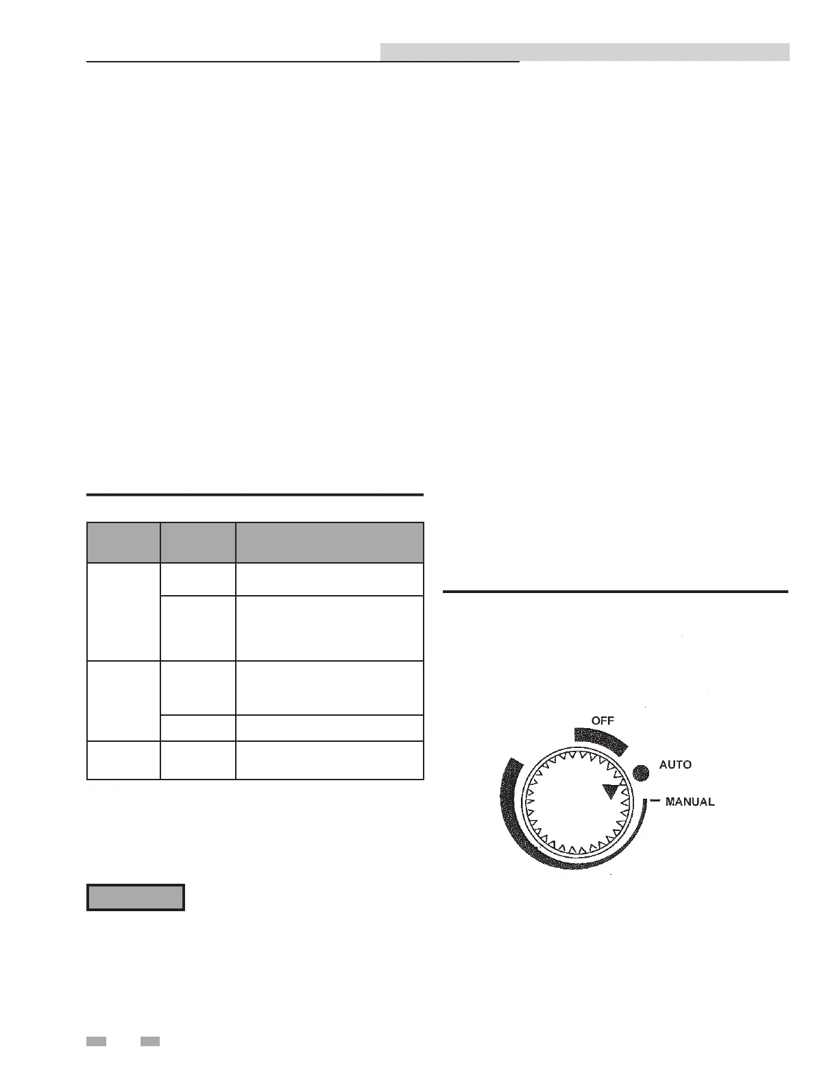
Manual control of 3-way valve - removable handwheel
to hamper tampering
If desired, the control path (A-to-AB) of the control valve can
be opened manually up to 95% of full-stroke. Reference FIG.
4-4 and proceed as follows:
1. Remove the water heater from service prior to using the
Manual Operating Mode.
2. Press the handwheel inward and rotate it clockwise to the
MANUAL position. This will disable the 0 to 10 VDC
control signal from the temperature controller. The valve
can now be mechanically rotated. The temperature control
system is now disabled. Be sure to return to the Auto Mode
prior to returning the system to heating service use (see
Step 4).
3. To disable automatic control of the valve, press the
handwheel inward and rotate it counterclockwise to the
OFF position. This will close the valve.
4. To set the valve for automatic (AUTO) operation, rotate
the handwheel to the AUTO position. The handwheel will
pop up when in the AUTO position, thereby allowing it to
be controlled by the temperature controller.
Table 4A Control Valve LED Status Indicators
LED
Display
Status Description
LED green
On
Continuously
Automatic Mode (normal, no faults)
Flashing
- Mechanically set to MANUAL
- Mechanically set to OFF
- Currently in Auto-Calibrate Mode
LED red
On
Continuously
- General fault
- General calibration fault
- Microprocessor fault
Flashing - Faulty 24 VAC supply (too low)
LED Off
- No 24 VAC supply
- Electronics module fault
9. Turn off power to the control valve by setting the control
box POWER switch to the OFF position.
10. Replace and secure the electronics module cover by
tightening the two (2) captive screws.
⚠WARNING
Manual control operation of the 3-way
valve disables the over-temperature and
power loss safety shutdown features of the
system. Manual operation is only used
for problem diagnosis. Manual operation
may cause over-heating of domestic water
and scalding of water users.
Figure 4-4 Control Valve Auto, Manual, and Off Positions
Indirect Plate Water Heater Installation & Service Manual
 Loading...