8
3 Hydronic piping
IPW piping assemblies
The diameter of the piping assemblies furnished with the
water heater will depend on the size of the heat exchanger
installed in the model ordered. Smaller sized models utilize
2" piping assemblies, while all other sizes utilize 3" and 4"
piping assemblies used in each double-wall model. See Table
3A for sizing of piping assemblies used in each double-wall
model.
General piping information
In addition to the heat exchanger and piping components,
each IPW piping assembly contains a number of other
important components and assemblies:
• Recirculation Pump (Continuously ON)
• Isolation
• Strainers (Boiler Water & DHW Sides)
• Blow-down Valves
• Pressure & Temperature (P & T) Relief Valve
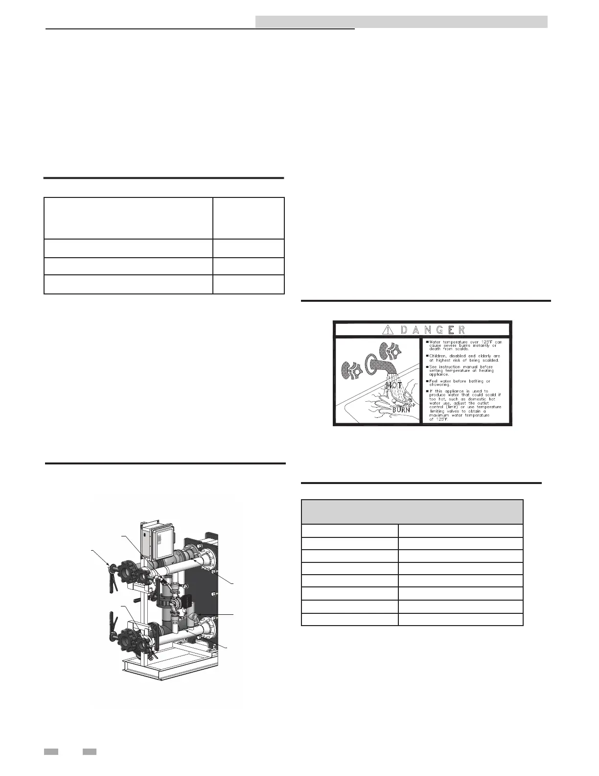
Figure 3-1 illustrates the locations of the above mentioned
components for a double-wall heat exchanger.
ISOLATION VALVES
(4 PLACES)
OUTLET RTD
INLET RTD
P & T RELIEF VALVE
BOILER WATER STRAINER
W/BLOW-DOWN VALVE
DOMESTIC WATER STRAINER
W/BLOW-DOWN VALVE
DIR #2000577647
Figure 3-1A Typical IPW Piping
Heating fluid and Domestic Hot Water
(DHW) piping
The diameter of the heating fluid (hot boiler water) and DHW
piping will depend on the model number and size of the water
heater being installed. Reference Table 3A (this page) for
applicable piping sizes.
Table 3A IPW Piping Assemblies
Model
Piping
Assembly
Diameter
IPW015 - IPW050 2"
IPW070 - IPW090 3"
IPW105 - IPW120 4"
Indirect Plate Water Heater Installation & Service Manual
Scalding
This water heater can deliver scalding temperature water at any
faucet in the system. Be careful whenever using hot water to avoid
scalding injury. Certain appliances such as dishwashers and
automatic clothes washers may require increased temperature
water. By setting the thermostat on this water heater to obtain
the increased temperature water required by these appliances,
you may create the potential for scald injury. To protect against
injury, you should install a mixing valve in the water system.
This valve will reduce point of discharge temperature by mixing
cold and hot water in branch supply lines. Such valves are
available from the local plumbing supplier.
Figure 3-1B Scald Warning
The following chart (Table 3B) details the relationship of water
temperature and time with regard to scald injury and may be
used as a guide in determining the safest water temperature for
your applications.
APPROXIMATE TIME / TEMPERATURE
RELATIONSHIPS IN SCALDS
120°F More than 5 minutes
125°F 1 1/2 to 2 minutes
130°F About 30 seconds
135°F About 10 seconds
140°F Less than 5 seconds
145°F Less than 3 seconds
150°F About 1 1/2 seconds
155°F About 1 second
Table 3B Approximate Time / Temperature Scald Chart
Anti-scald mixing valve:
Field supplied. An anti-scald mixing valve is recommended
when domestic hot water supply is above 115°F.
 Loading...