K8
K0
K6
K7
K7
K7
K8
K7
K1
K1
ref.1
K2
K2
K2
only when unit is
cascaded
to
slave
boiler
to
master
boiler
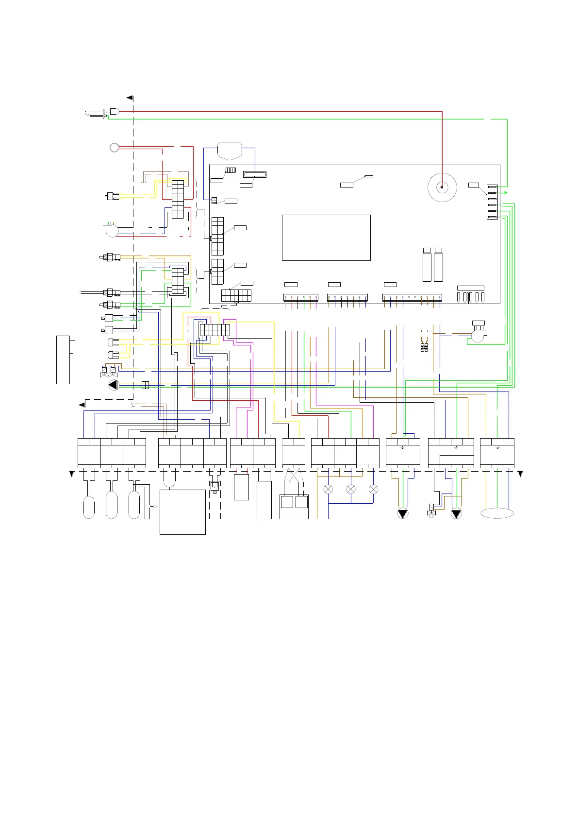
Remote temperature
setpoint or burner input
signal form BMS
water pressure
switch
Calorifier themostat
Calorifier
sensor 10K
External
flow sensor 10K
Outdoor
sensor 12K
connection
examples
POWER
SUPPLY
Heat demand
N.O.
Flame on
N.O.
Lock-out
N.O.
K4
K4
CN4
+
CN not used
1098
1 2 4
3 5 6
71 2 4
3 5 6
7
653
421
K5
K9
K9
K9
K6
K2
K2
K6
K2
K6
K2
K8
K6
K3
K8
K4
K7
K1
K0
K6
K6
K8
K8
K0
K0
K3
K3
K5
K5
K6
K2
K10
K6
K2
FAN
FAN
internal
connections
internal
connections
connection
examples
fuse 2
fuse 1
F2 F1
ref.1
N.C.
N.C.
boiler casing
CN10
[close]
N
boiler pump
(pump1)
gas valve(s)
Heat demand NO
ionisation and/or ignition
CN8
ignition
transformer incl.
ionisation input.
T2
CN7
display
CN6
Heat demand NO
OpenTherm/
power stealing
thermostat
fan control
fan PWM
fan Hall
+24Vdc
-
siphon pressure switch (PSW)
clixon/maximum (S6/S7)
water thermostat 24vdc
return sensor ntc (S2) 10K
flow sensor ntc (S1) 10K
CN5CN1CN3
CN12
14
13
12
11
10
9
8
7
6
5
4
3
2
1
12
11
10
9
8
7
6
5
4
3
2
1
CN10
CN11
2
3
4
5
6
7
8
16
15
14
13
12
11
10
1
2
3
4
5
6
7
8
9
10
11
12
1
2
3
4
5
6
7
8
9
10
11
12
13
14
MAINS L'
MAINS N'
Lock-Out NO
Flame on NO
Lock-Out NO
Flame on NO
Pump 3, N'
Pump 3, L'
Gas Valve, N'
Gas Valve, L'
Pump 1, L'
Pump 1, N'
Pump 2 / 3-way, L' (NO)
Pump 2 / 3-way, N'
[open] 3-way, L' (NC)
out
Gnd
1
9
17
18
18
17
9
1
10
11
12
13
14
15
16
8
7
6
5
4
3
2
L N
Mains 230 VAC
L N
CH System
Pump P3
BURNER
BURNING
+ -
0 - 10
VDC
On/Off Stat
or
OpenTherm
Heating
Circuit
343332272625212019161514136
54
321
GENERAL
BLOCKING
22 23 24
HEAT
DEMAND
LOCK-OUT
N.O. N.O.N.O.
EXTERNAL
FLOW
SENSOR
CALORIFIER
SENSOR
or
THERMOSTAT
7
8 9 10 11 12
EXTERNAL
WPS
OUTDOOR
SENSOR
17 18
A B
CASCADE
CONNECTION
28 29 30 31
CN15
EMPTY
K8
K6
K8
K6
K3
L1 N L2
Divertor Valve Calorifier
by Calorifier Pump P2
K2
wire
bridge
External safety device:
- External flow switch
- Smoke detection
- Gas detection
- Ventilation fan
- Flue gas fan
- End switch motor actuated
flue gas valve
- Gas leakage tester
- etc
WIRING COLORS
K0=white K6=blue
K1=yellow K7=red
K2=brown K8=black
K3=green K9=purple
K4=grey K10=yellow/green
K5=orange
K10
K10
K10
K10
K10
K8
K8
Therm.stat 230v
Therm.stat 230v
pump
connector
flue sensor ntc (S5) 10K
water pressure sensor
(water pressure switch will
be mounted above 4 Bar)
+5V
out
Gnd
N.C.
rear wall thermal
fuse
K1
K1
(water pressure switch
connection) Not used
Model 60 has no thermal fuse
and no thermal switch.
Both connections are bridged.
N.C.
burner door thermal
switch
 Loading...