the display. When no button is activated for 2 minutes the display will return to its status display.
Pressing [◄] or [►] when the display shows the "operating screen" toggles through the screens below.
Pressing [ON/OFF, RESET, ENTER] or [MENU] at any time returns the display to the base menu.
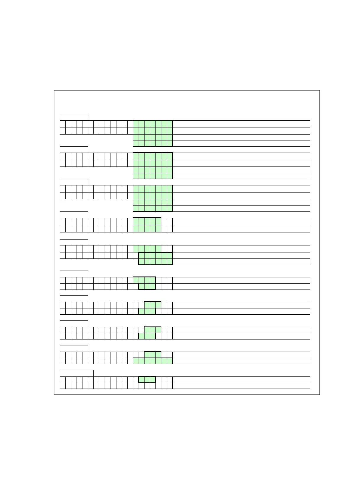
SCREEN: 1
T 1 F l o w 1 2 3 , 9
o
C Temperature measured by the internal flow sensor.
T 2 R e t u r n 1 2 3 , 9
o
C Temperature measured by the internal return sensor.
O p e n Shown when the controller does not detect this sensor.
S h o r t e d Shown when the sensor wires or the sensor itself is shorted.
SCREEN: 2
T 3 E x t e r n a l 1 2 3 , 9
o
C Temperature measured by the external sensor.
T 4 C a l o r i f i 1 2 3 , 9
o
C Temperature measured by the calorifier sensor.
O p e n Shown when the controller does not detect this sensor.
S h o r t e d Shown when the sensor wires or the sensor itself is shorted.
SCREEN: 3
T 5 O u t d o o r 1 2 3 , 9
o
C Temperature measured by the outdoor sensor.
T 6 F l u e 1 2 3 , 9
o
C Temperature measured by the flue gas sensor.
O p e n Shown when the controller does not detect this sensor.
S h o r t e d Shown when the sensor wires or the sensor itself is shorted.
SCREEN: 4
d T F l o w R e t u r n 1 2 3 , 9
o
C Temperature difference between internal flow & internal return sensor.
d T F l u e R e t u r n 1 2 3 , 9
o
C Temperature difference between flue gas & internal return sensor.
SCREEN: 5
d T E x t R e t u r n 1 2 3 , 9
o
C Temperature difference between external & internal return (ΔT LLH).
S i g n a l P o w e r External supplied 0-10 Volt dc signal.
S e t p o i "Power" = power output control or "Setpoi" = temperature setpoint control.
SCREEN: 6
F a n s p e e d 9 9 9 9 r p m Actual fan speed in rpm.
F a n s p e e d 1 0 0 % Actual fan speed % of maximum allowable fan speed.
SCREEN: 7
F l a m e s i g n a l 1 0 0 μ A Flame signal given in μA.
W a t e r P r e s s u r 1 , 0 b a r Shows water pressure when sensor is connected.
SCREEN: 8
P u m p 1 H e a t e r O f f Pump 1 (Internal pump) On or Off.
P u m p 1 S i g n a l 1 0 0 % Modulating signal Pump 1 in (% ).
SCREEN: 9
P u m p 2 C a l o r i O f f Pump 2 (Calorifier pump) On or Off.
3 - w a y V a l v e H e a t i n g Signal to the 3-way valve: "HEATING" or "HOTWATER".
SCREEN: 1 0
P u m p 3 S y s t e m O f f Pump 3 (Sy stem pump) On or Off.
h h : m m D D / M M / Y Y Y Y D a y Time & Date: hh=hour; mm=minutes; DD=date; MM=month; YYYY=y ear; Day
 Loading...