16.8 SETTING A REPLACEMENT GAS VALVE
When a replacement gas valve is fitted, the following procedure must be carried out in the order stated when the
boiler is switched on for the first time. Failure to follow the following procedure may lead to non-warrantable
damage to the boiler.
Number of Turns Open
(Counterclockwise)
* Both gas valves must be opened this number of turns
TABLE 16.1 PRE-ADJUSTMENT OF GAS VALVES
“p-out” Pressure at Gas Valve
TABLE 16.2 PRESSURE ADJUSTMENT OF LEFT GAS VALVE
2
All values are measured without boiler door.
TABLE 16.3 COMBUSTION GAS READINGS
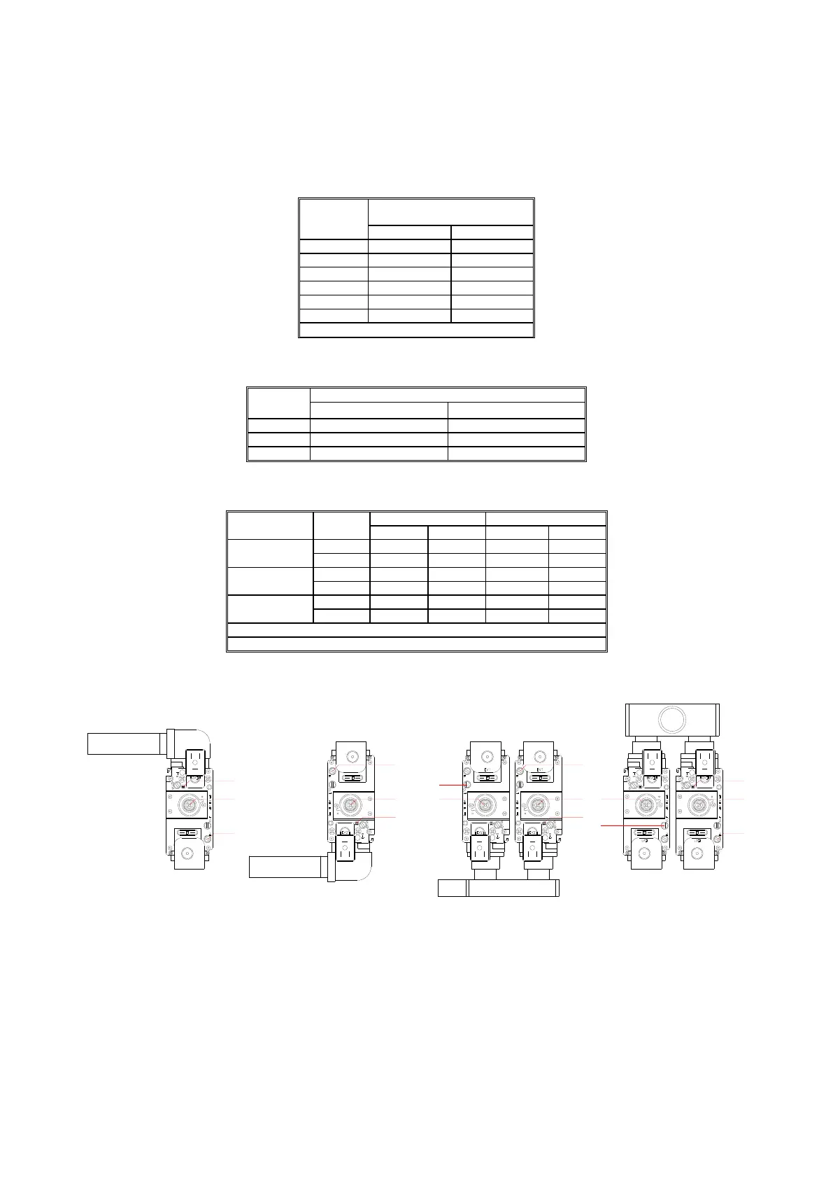
FIGURE 16.1 GAS VALVES
1. Turn screw 2 (Figure 16.1) clockwise until fully closed. On models with two gas valves, this should be
done to both valves.
2. Turn screw 2 counter clockwise in accordance with Table 16.1. On models with two gas valves, this
should be done to both valves.
3. On models CP-M+120, CP-M+150 & CP-M+180, remove the screw from the outlet pressure test point of
the left hand gas valve (identified as screw 4 in Figure 16.1) and attach a manometer.
3
1
2
3
1
2
3
1
2
2
1
3
CP-M+60
CP-M+80 & 100
CP-M+120
CP-M+150 & 180
1
4
1
4
 Loading...