DYNAMIC MOTION SYSTEM - SYSTEM MANUAL // PAGE 10
4 ASSEMBLY
This chapter of the Operating Manual describes the process of connecting the table system’s components
after they have been mounted to the Height-Adjustable Table System. You must read the documentation for
each part of the system (Actuator, User Interface, Power Hub, etc.) for that product’s mounting instructions
The chapter "Assembly" outlines common congurations for Table Systems. For further information con-
cerning other congurations of the DYNAMIC MOTION system, contact LOGICDATA.
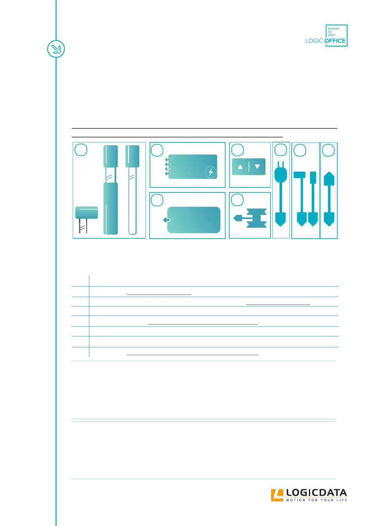
Fig. 1: Required components. NOTE: This is a summary list of the components used in the dierent
installation variants of the DYNAMIC MOTION system. Not all components are required for all
variants.
1 DYNAMIC MOTION Actuators (should be mounted into Height-Adjustable Columns)
2a Power Hub (Optional - See Chapter 4.7)
2b DYNAMIC MOTION-compatible external power supply (Optional - See Chapter 4.7)
3 User Interface (Handset or other)
4 Benching Adapter (for Benching Table Systems - see Chapter 4.3)
5 Power Cable (Must be compatible with the installed Power Hub and Domestic Mains Supply)
6 DMLIN Actuator Cable (1 per actuator)
7 Sync Cable (for Tables with Multiple Power Hubs - see Chapter 4.4)
INFO
Your Table System must be powered using a DYNAMIC MOTION-compatible Power
Unit. A Power Unit is a general term that covers DYNAMIC MOTION Power Hubs
and all DYNAMIC MOTION-compatible external power supplies. The assembly
process diers slightly depending on which type of Power Unit will be installed.
Unless otherwise stated, the instructions in this Manual assume that the user has
installed a Table System alongside a Power Hub that adapts Mains electricity. If you
have purchased a DYNAMIC MOTION system for use alongside a DYNAMIC MOTION-
compatible external power supply, you are obliged to read that product's Manual in full.
INFO
Your Table System must be controlled using a DYNAMIC MOTION-compatible User
Interface. A User Interface is a general term that covers Handsets (Basic, Comfort,
Paddle) and other products that can control the System, e.g. LOGIClink. Assembly
and Operation dier depending on which type of User Interface will be installed.
Unless otherwise stated, the instructions in this Manual assume that the user has in-
stalled a Table System alongside a Comfort or Basic Handset. If you have purchased a
DYNAMIC MOTION system for use alongside a dierent User Interface, you are obliged
to read the Manual of your chosen User Interface in full.
DMPxxx
1
42b
2a 3 5 76