DYNAMIC MOTION SYSTEM - SYSTEM MANUAL // PAGE 18
4.5 CONNECTING POWER HUBS
The DYNAMIC MOTION system can be connected to the Mains via a DYNAMIC MOTION Power Hub and
Power Cable (see Chapter 4.1.2). The connections to the Power Hub depend on the type of Table System used.
Read the assembly instructions for your Table System for more details.
Power Cables are ordered separately. Contact LOGICDATA to ensure you Power Cable is compatible with
your selected Power Hub and your domestic mains supply (EU/US, etc.).
4.6 CONNECTING EXTERNAL POWER SUPPLIES
The DYNAMIC MOTION system can be powered using LOGICDATA-approved, DYNAMIC MOTION-
compatible External Power Supplies. For instructions and safety advice, consult your product's operating
manual.
4.7 PERFORMING A POSITION RESET PROCEDURE
CAUTION
Risk of minor or moderate injury through crushing
Collision Detection (ISP) is inactive during start-up and reset processes. This may lead
to minor or moderate injury through crushing.
• Ensure that no persons or objects are in the table's range of motion
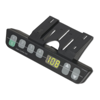
It is possible to perform a Position Reset Procedure with all types of compatible User Interface. However,
this section describes performing a Position Reset Procedure for Table Systems controlled by a Handset with
an UP Key and DOWN Key (Comfort or Basic Handsets).
If your DYNAMIC MOTION system is operated by a dierent User Interface, consult that product’s operating
Manual for instructions on performing a Position Reset Procedure.
1. Press and hold the DOWN Key until the table stops at the lower position limit
2. Release the DOWN Key
3. Press and hold the DOWN Key again
The table will move down slightly, then up again
4. Release the DOWN Key
The Position Reset Procedure is complete.
INFO If your DYNAMIC MOTION system has been parameterized with additional stop-
ping points (e.g. a Safety Area or Container Stop Position), repeat Step 3 until the
table has moved upwards again.