DYNAMIC MOTION SYSTEM - SYSTEM MANUAL // PAGE 13
4.2 ASSEMBLY: TABLE SYSTEM WITH 1 POWER HUB
This chapter describes assembly for Table Systems with one Power Hub and 1, 2, 3, or 4 Height-Adjustable
Columns (not Benching Systems). The Table Top and Height-Adjustable Columns are supplied by the Reseller.
4.2.1 REQUIRED COMPONENTS
1 to 4 Height-Adjustable Columns with DYNAMIC MOTION Actuators
1 DMLIN Actuator Cable per Actuator
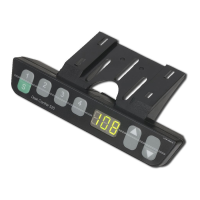
1 User Interface (Handset or other)
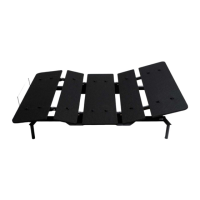
1 Power Hub
1 Power Cable
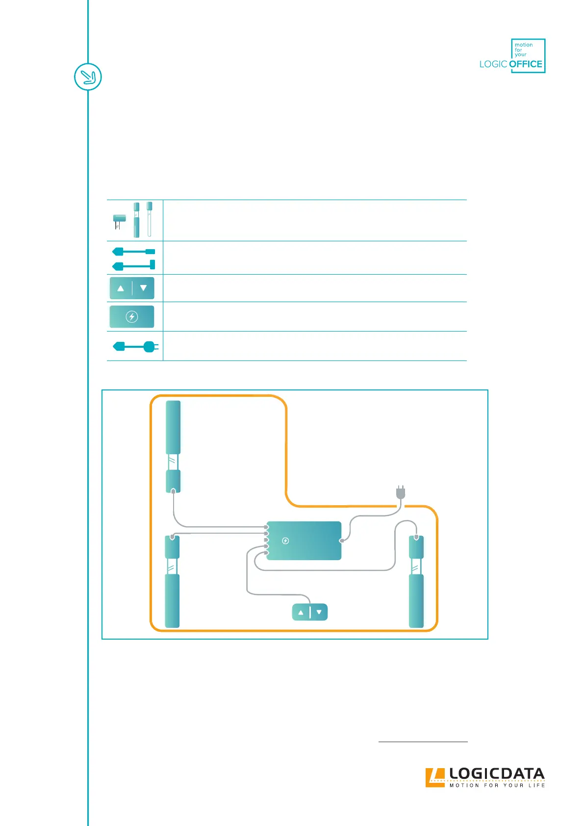
4.2.2 CONNECTING THE COMPONENTS
Fig. 3: Connection map (example with a DMP360 and 3 Height-Adjustable Columns)
1. Plug the Actuator(s) into the Power Hub
2. Plug the User Interface into the Power Hub
3. If a Power Hub is used, plug the Power Hub into the Mains
4.2.3 COMPLETING ASSEMBLY
Before you use the table, you must perform a Position Reset Procedure (see Chapter 4.7 page 18).
DMP240
DMP360