8
3.5 Installation and connection of the cables
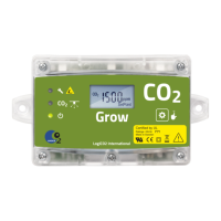
The different units are connected to each other by cables. The blue marked cable is used for
signalisation (horn/strobe, warning beacon and remote control box). The red marked cable is for
communication and power. Please observe, all cables have splitters at the end to facilitate extended
cable lengths. When installing, the cables may need to be disconnected for purposes of cable routing.
When reconnecting, please make sure that you connect to the original splitters and connectors. Make
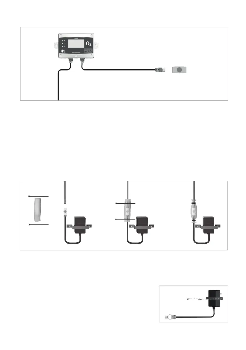
sure to mount the protective collar seals with the tie-wraps in order to protect the connections from
dirt and water. The collar seals as well as the tie-wraps are also delivered in the box that the sensor
comes in. If possible, route the cables through cable conduits between the units, for a neat and safe
installation.
Protective collar seals and cable ties are included. They must be used as below to protect the RJ45 1-1
connector or RJ45 1-2 splitter from moisture and dust.
3.6 Connection of the power supply
A separate power supply (100-240 VAC) supplies power to the system. Please observe that you have
to connect the appropriate plug adaptor to the power supply depending on which country you are in.
Connect the power supply to the electrical outlet.
Mount the included plug-lock so that the power supply cannot be
disconnected without the use of tools.
It is also possible to order a hardwired power supply option when
and were it is needed.
Blue
Red