Chapter V Disassembly & Repair
- 55 -
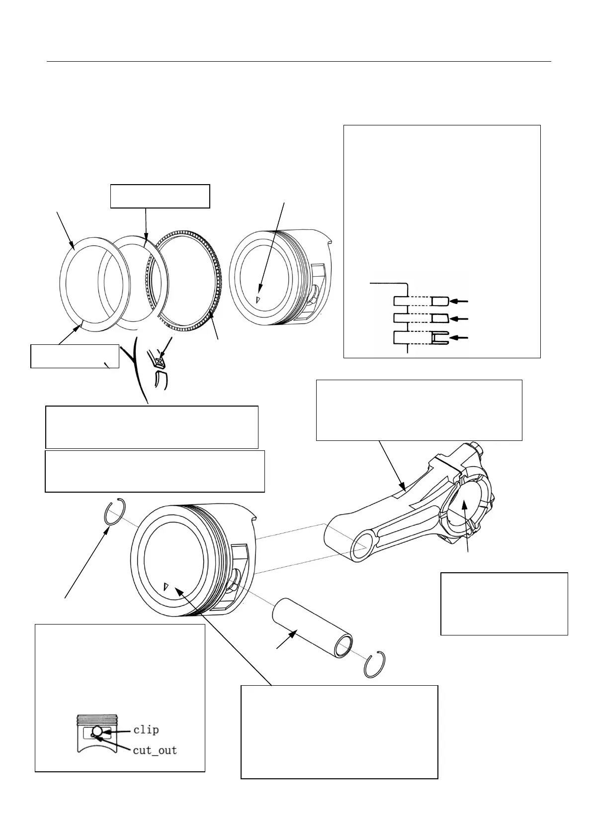
Disassembly/assembly
Piston and connecting rod
Ring 1
Ring 2
Ring 1
Opening of ring 1
Opening of ring 2
Ring 2
Oil rings
Note: point the “
▽
” at the top of the piston
to the opposite direction of rotation of the
crankshaft (seen from the engine output
end, the piston arrow of the right cylinder
is downward while the piston arrow of the
left cylinder is upward)
.
Note:
Openings of rings 1 and 2 shall be staggered
for 150° ~ 210°.
Note:
Opening of blade ring of oil ring shall be
staggered for 150°~ 210°.
Connecting rod
Steel wire retaining ring
Piston mark
Piston pin
Assembly:
Put one end to the slot of the piston,
and clamp the other end with the
long nose pliers; rotate and install it
into the slot. Don’t make the
opening of the clamp ring face the
gap of the piston pin.
Assembly:
p
oint the “ ” mark of the
piston to the same direction of that of the
connecting-rod boss during assembly while
the other is in the opposite direction.
Bigger end hole
Mark
Coat adequate lubricating
oil on the bigger end hole
of the connecting rod in a
full circle.
Assembly:
. Put upward the manufacturer’s mark
during assembly.
. Do not misplace the gas rings 1 and 2.
. Check if the piston ring can rotate
flexibly after installation.
. Avoid the direction of piston pin for each
opening of piston ring by staggering for
150° ~ 210°.