Chapter V Disassembly & Repair
- 54 -
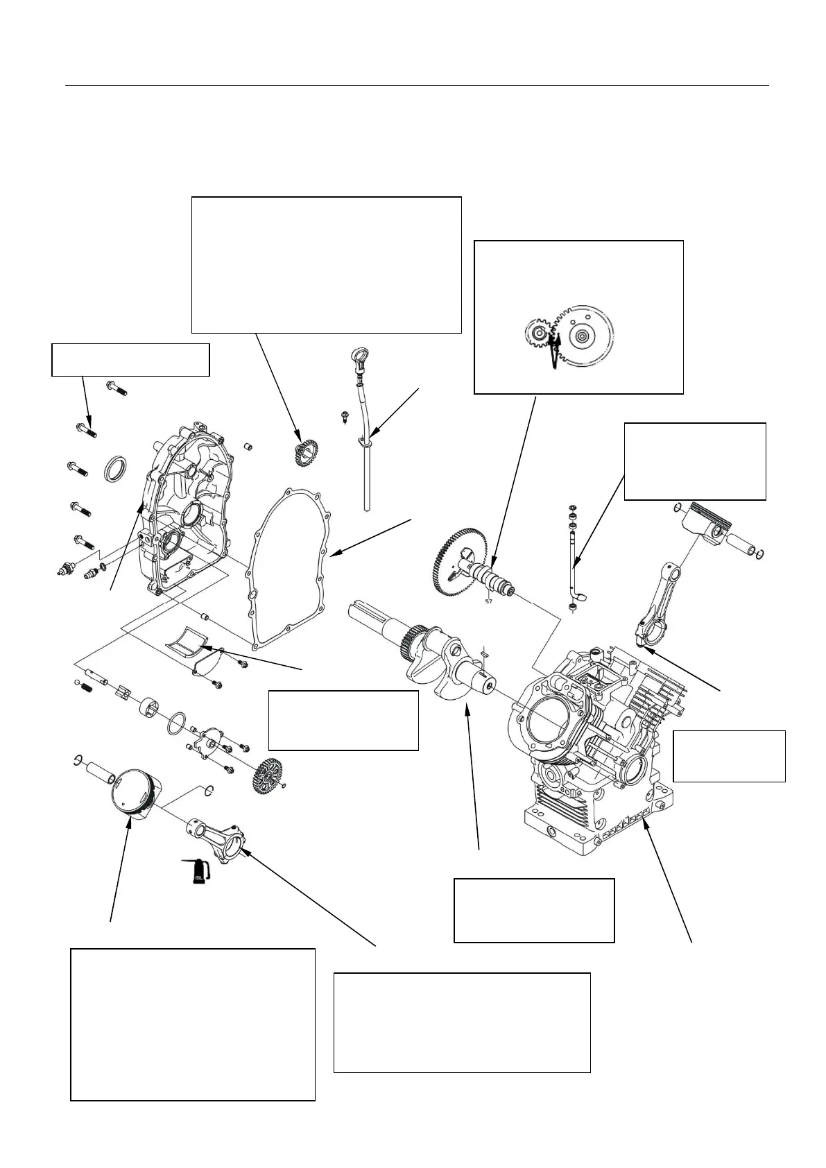
5-2-9 Crankcase, crankshaft and piston
Disassembly/assembly
Assembly:
▽
Point the “ ” mark at the top of the
piston to the opposite direction of
rotation of crankshaft (seen from the
output end of engine, the piston
arrow of the right cylinder is
downward and the piston arrow of
the left cylinder is upward).
Piston
Speed-regulating arm
Camshaft
Align the gear of camshaft
with the timing gear on the
crankshaft during installation.
Comparison mark
Bolt M8 × 50
Crankshaft part
Assembly:
Don’t damage the oil
seal during installation.
Connecting rod
Assembly: coat adequate lubricating oil
on the bigger end hole in a full circle.
Connecting-rod boss has the same
direction with that of the piston arrow
while the other is opposite.
Connecting-rod
Crankcase body
Torque: (25 ~ 30) N•m
Crankcase-cover
sealing gasket
Torque:
12 N.m±1 N.m
Oil-level
Assembly:
Confirm if the
action is smooth
Assembly:
. Check if the speed-regulating gear is
worn or damaged prior to installation.
. Confirm if the speed-regulating gear
rotates flexibly without obvious axial
drifting after installation.
Dirty or damaged one
shall be cleaned or
Crankcase cover
Speed-regulating gear