EasyManua.ls Logo

LORCH T BasicPlus Series User Manual

LORCH T BasicPlus Series
242 pages
Go to English
To Next Page IconTo Next Page
To Previous Page IconTo Previous Page
Page #65 background image
Puesta en marcha
- 65 -
01.21 909.2669.9-02
Ajuste del ID del soplete
En cada soplete de la serie i-LTG/i-LTW se encuentra almace-
nado un número de identicación de soplete. A este ID de
soplete se encuentra asociada la capacidad de carga máxima
del soplete. Con la protección de soplete activada (parámetros
secundarios tPr” = On), en el modo de operación WIG, solo
puede ajustarse en el aparato de soldar una corriente de sol-
dadura con la máxima capacidad de carga del soplete.
El ajuste del ID del soplete es necesario p. ej. al cambiar la
placa del soplete.
 Seleccione el menú nº C00 en el menú especíco del usua-
rio.
 Ajuste en el regulador giratorio 41 el ID del soplete necesa-
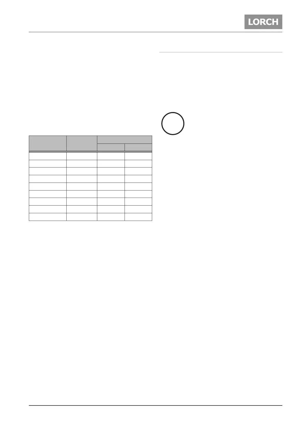
rio, basándose en la tabla de ID de soplete.
Tipo de soplete
ID de so-
plete
Capacidad de carga
CC CA
i-LTG 900 9 125 A 80 A
i-LTG 1700 17 150 A 120 A
i-LTG 2600 26 200 A 160 A
i-LTG 2800 28 300 A 250 A
i-LTW 3000 30 320 A 220 A
i-LTW 1800 18 350 A 250 A
i-LTW 1800sc 19 400 A 320 A
i-LTW 2000 20 220 A 165 A
i-LTW 4500 45 450 A 360 A
Tab. 6: ID de soplete
 Para guardar, pulse la tecla que se encuentra a la derecha
bajo el parámetro principal 48.
9 El ID de soplete ajustado se transere al soplete.
14.6 Funciones especiales
Test de gas, test de panel de mando
 Pulse simultáneamente la tecla superior derecha Modo de
operación 47 y la tecla inferior derecha Parámetro princi-
pal 48; el test de gas se iniciará en aprox. 30 segundos. Al
mismo tiempo se iluminarán brevemente todos los LEDs y
la indicación de 7 segmentos.
 Pulsando de nuevo ambas teclas el test de gas nalizará.
Reset principal
Todos los parámetros de soldadura y secunda-
rios retomarán el ajuste de fábrica (Función de
reset principal)
 Pulse la tecla Soldadura 30 arriba a la izquierda y mantén-
gala pulsada.
 Al mismo tiempo, pulse brevemente la tecla
 Parámetro principal 48 abajo a la derecha.
9 LED y las indicaciones de 7 segmentos se iluminan breve-
mente.
i
i

Table of Contents

Question and Answer IconNeed help?

Do you have a question about the LORCH T BasicPlus Series and is the answer not in the manual?

LORCH T BasicPlus Series Specifications

General IconGeneral
BrandLORCH
ModelT BasicPlus Series
CategoryWelding System
LanguageEnglish

Summary

Machine Elements and Identification

Explanation of Symbols

Symbols in Operation Manual

Explains symbols used within the operation manual for safety and information.

Symbols on the Machine

Details symbols found directly on the welding machine for warnings and operation.

Safety Precautions

General Safety Guidelines

General safety guidelines for operating the welding machine, including workspace preparation and personal protection.

Electrical and Environmental Safety

Safety measures related to electrical hazards, rain exposure, and environmental conditions.

Personal Protective Equipment

Essential personal protective equipment and precautions for welding operations.

Operational Safety Checks

Checks and precautions for safe operation, including fire safety and cable integrity.

Transportation and Setup Safety

Safety guidelines for transporting and setting up the welding machine on stable surfaces.

Ambient Conditions for Operation

Operating Environment Specifications

Specifies temperature, humidity, and air quality requirements for machine operation and storage.

General Usage Regulations

Intended Applications and Materials

Details the materials and welding processes the device is intended for use with.

UVV Inspection Requirements

Unit Protection Features

Electromagnetic Compatibility (EMC)

EMC Compliance and Interference Sources

Details EMC standards compliance and lists common sources of electromagnetic interference.

Mains Connection Requirements

Mains Connection Standards and Warnings

Explains compliance with EN/IEC standards and provides warnings for mains connection and usage.

Noise Emission Levels

Transport Guidelines and Warnings

Safe Transport Methods

Provides instructions on safe methods for transporting the welding machine using lifting equipment or by hand.

Before Commissioning

Fastening the Transportation Belt

Step-by-step guide for correctly attaching the transportation belt to the welding machine.

Fastening the Accessories Belt

Instructions for securing the accessories belt to the welding machine's handle.

Electrode Welding Process Setup

Connecting the Electrode Cable

Procedure for connecting the electrode cable to the welding machine.

Connecting the Power Supply

Instructions for connecting the machine to the mains supply or a current generator.

Connecting the Ground Cable

Steps for correctly connecting the ground cable to the welding machine.

TIG Welding Process Setup

Connecting the Torch

Procedure for connecting the TIG torch to the welding machine.

Inserting the Electrode

Guide on how to properly insert the tungsten electrode into the torch.

Connecting the Shielding Gas Cylinder

Shielding Gas Cylinder Setup Procedures

Detailed steps for securing the cylinder, connecting the regulator and hose, and performing a gas test.

Control Panel Overview

Welding Process Selection

Details the selection switch and LEDs for choosing welding processes like TIG-DC/AC and electrode welding.

Machine Mode Selection

Explains the selection switch and LEDs for choosing operating modes like 2-stroke, 4-stroke, or Pulse.

Welding Parameter Adjustment

Describes the selection switch, knob, and display for adjusting welding parameters.

Gas Pre-flow Time Control

Information on the LED indicating gas pre-flow time and its adjustment.

Upslope Parameter Control

Details the LED for upslope and how to adjust the upslope time.

Main Current (I1) Control

Explains the LED for main current and its adjustment using the control knob.

Pulse Frequency Control

Information on the LED for pulse frequency and its adjustment.

Second Current (I2) Control

Details the LED for the second current and its adjustment.

Downslope Parameter Control

Explains the LED for downslope and its adjustment.

Gas Post-flow Time Control

Information on the LED indicating gas post-flow time and its adjustment.

Starting Up the Welding Machine

Electrode Welding Process Setup

Steps for selecting the electrode welding process and setting the main current.

TIG Welding Process Setup

Steps for selecting the TIG welding process and desired mode, then setting parameters.

Secondary Parameters Adjustment

Secondary Parameter Adjustment Procedures

Explains how to access and set secondary parameters, including safety warnings.

Hotstart and Arc Dynamic Settings

Details adjustment of hotstart, hotstart time, and arc dynamic for welding.

Start and Final Current Settings

Covers setting start current, start current time, final current, and final current time.

Pulse and AC Welding Parameters

Explains settings for pulse duty factor, AC balance, AC frequency, and positive current correction.

Powermaster Parameters

Powermaster Parameter Selection

Guide on selecting and adjusting Powermaster parameters like torch-ID and welding current limits.

Parameter Settings Overview

Details specific Powermaster parameters including gas pre-flow, start current, upslope, and more.

User-Specific Menu

Accessing and Setting User Menu

Instructions on how to access, navigate, and set values within the user-specific menu.

Torch-ID Adjustment

Torch-ID Configuration

Procedure for adjusting the torch-ID via the user menu, referencing the torch-ID chart.

Special Functions

Gas and Control Panel Test

How to perform a gas test and a control panel test using specific button combinations.

Master Reset Procedure

Instructions for resetting all parameters to factory default settings.

Torch Functions and Operation

Torch Switch Functions

Details the functions of the torch switches for start/stop, current selection, and parameter adjustment.

Torch Display and Indicator LEDs

Explains the functions of the torch display, indicator LEDs (Amperage, Job), and Powermaster LEDs.

Stick Electrode Welding

Stick Electrode Welding Process

Describes the stick electrode welding process, electrode coating, and electrode types.

TIG Welding Process

TIG Welding Process Basics

Explains the fundamentals of TIG welding, including the tungsten electrode, shielding gas, and arc formation.

Tungsten Electrode Tip Shaping

Guidance on shaping the tungsten electrode tip for DC and AC welding, including a table of angles.

TIG Welding Materials and Current Modes

Discusses materials welded with TIG and the use of DC and AC current modes.

Technical Data - Part 1

Welding Range and Current Specifications

Presents technical data for welding range, idle voltage, current settings, and consumption.

Power Consumption and Electrode Data

Details power consumption figures and the range of weldable electrode diameters.

Technical Data - Electrical and Physical Specs

Mains and Power Specifications

Provides data on mains voltage, frequency, tolerance, connection, fuse, power factor, and impedance.

Protection, Cooling, and Dimensions

Details protection class, insulation class, cooling method, noise emission, norm, designation, and physical dimensions.

Technical Data - Extended Specifications

Extended Welding Range and Current Data

Presents technical data for extended welding ranges, idle voltage, and current consumption.

Power Specifications and Electrode Compatibility

Details power consumption, mains tolerance, and weldable electrode sizes for various models.

Messages and Error Codes

Informative Messages (H01-H10)

Lists informative messages with their meaning and recommended actions for troubleshooting.

Error Messages (E01-E34)

Overload and Overvoltage Error Codes

Details error codes related to thermal overload, overvoltage, and PFC issues.

Connection and Component Error Codes

Lists error codes for connection faults, torch monitoring, and component issues.

Voltage, Current, and Ignition Errors

Covers error codes related to voltage, current detection, overcurrent, and ignition device.

System and Configuration Error Codes

Details error codes for supply voltage, configuration, user panel, power unit, and fan.

Maintenance and Repair

Regular Maintenance Checks

Outlines regular checks for damage, dust filter maintenance, and the use of genuine spare parts.

Repair and Service Guidelines

Provides guidelines for handling problems and repairs, emphasizing authorized service.

Disposal Instructions

Environmentally Friendly Disposal

Instructions for the proper disposal of electric tools in EU countries according to environmental regulations.

Service and Support Information

Contact and Download Information

Provides company contact details and a link to the Lorch Download-Portal for documentation.

Certificate of Conformity

Product Compliance Declaration

Declaration of conformity stating the product meets specified norms and guidelines.

Related product manuals