page 43
Identication power units
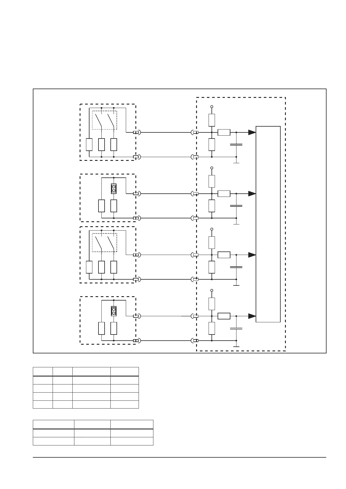
The pc-board DK-MAPRO is reading the conguration of the power units during the initialisation. On the primary
sides (pc-board DCDRV) the conguration is set by a DIP switch. On the secondary sides at AC/DC machines
(pc-board ACDRV) the conguration is set by a small jumper. The secondary side of the DC machines are the pc-
board KSDCN, which have a xed (not setable) conguration.
If the DK-MAPRO detects a non valid conguration, it will display the error code E25 (Powermodul detection).
Schematic
+3.3V
+3.3V
+3.3V
+3.3V
DSP
1 2
1 2
X1 / 4
X2 / 4
DCDRV2
DK-MAPRO
X2 / 11
DCDRV1
ACDRV1
X1 / 11
X1 / 4
X1 / 11
X6 / 14
X6 / 10
X6 / 14
X6 / 10
ACDRV2
X4 / 14
X4 / 10
X3 / 4
X3 / 11
X5 / 14
X5 / 10
primary side (on DCDRV boards)
DIP 1 DIP 2 setting type
OFF OFF 240 A V24, V40
OFF ON 270 A V27
ON OFF 300 A V30, V50
ON ON reserved
secondary side (on ACDRV boards)
J1 setting type
0 (jumper not set) 2 IGBT V24, V40
1 (jumper set) 4 IGBT V27, V30, V50