page 18
Pc-board DK-ACDRV
The pc-board DK-ACDRV is managing the drive level for the secondary inverter (AC power module with IGBT
full-bridge)
Functions
- encoding AC power unit
- drive level IGBTs
- connection of temperature sensor
Encoding power unit
J1 setting machine type
0 2 IGBT V24, V40
1 4 IGBT V27, V30, V50
(0 = contact open ; 1 = contact closed)
LEDs
The LEDs on the pc-board DK-ACDRV are showing the drive level state of the IGBT.
LED on IGBT not driven
LED o IGBT driven
Measuring points
designation measure point result
temperature sensor X5/1
X5/2
+
GND
10kW at 25°C
(about +2V DC)
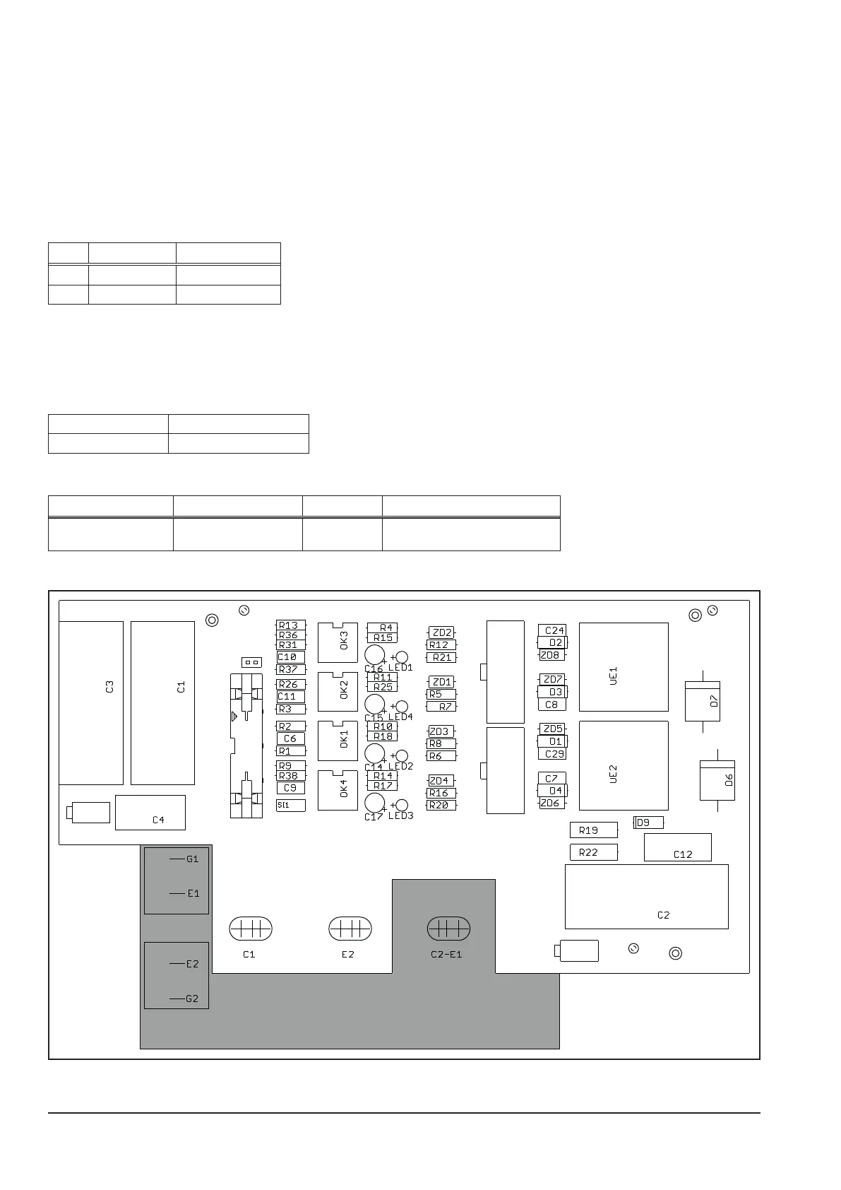
Picture pc-board DK-ACDRV
IGBT
X2
X6
X1
X3
X5
J1