page 13
Pc-board DK-DCDRV
The pc-board DK-DCDRV is managing the primary drive level of the power unit.
Functions
- encoding power unit
- connection of the thermal sensor (at heat sink)
- supply current sensor
- monitoring bus voltage and supply voltage
- safety shut-down of power unit
- passthrough signal power-up relay
- passthrough output of current sensor
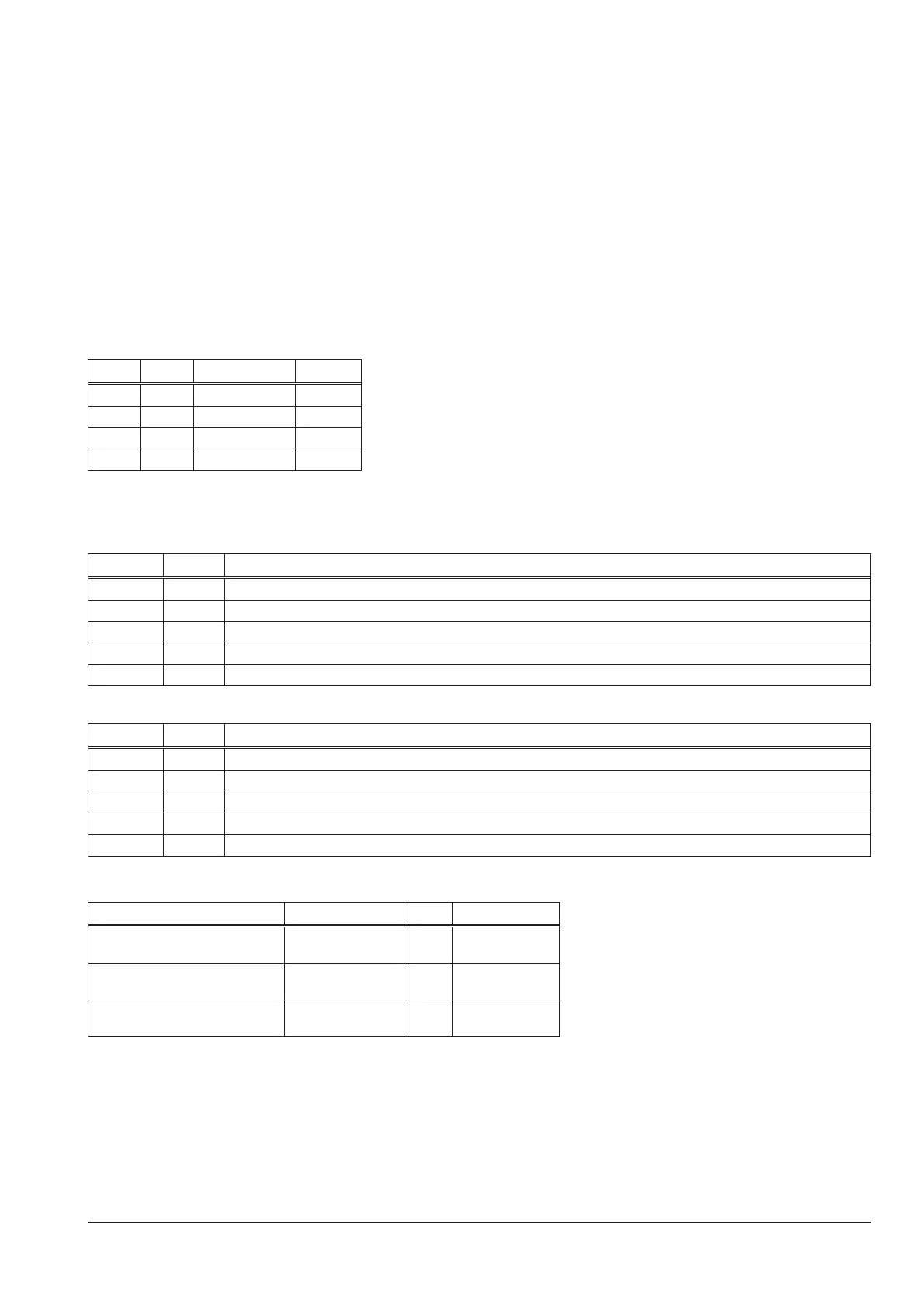
Encoding power unit
The type of the power unit is set via the DIP switch.
DIP 1 DIP 2 setting type
OFF OFF 240 A V24, V40
OFF ON 270 A V27
ON OFF 300 A V30, V50
ON ON reserviert
LED displays
normal
LED state designation
1 (red) o primary overcurrent shut down
2 (green) on drive level of low-side is ok
4 (green) on bus voltage max is ok
5 (green) on drive level of high-side is ok
6 (green) on bus voltage min is ok
malfunction
LED state reason
1 (red) on primary current is too high, power unit has been switched o
2 (green) never on no drive level low-side
4 (green) o bus voltage is too high (e.g. mains overvoltage)
5 (green) never on no drive level high-side
6 (green) o bus voltage is too low (e.g. mains voltage too low)
Measuring Points
designation measure point result
supply voltage current sensor X2/1
X2/6
+
gnd
+15V DC
supply voltage current sensor X2/3
X2/6
-
gnd
-15V DC
temperature sensor X3/1
X3/2
gnd
+
10kW at 25°C
(about +2V DC)