12
1.6 ELECTRICAL CONNECTION
When the appliance is delivered it is set to work at the voltage given
on the rating plate axed on the right side of the appliance.
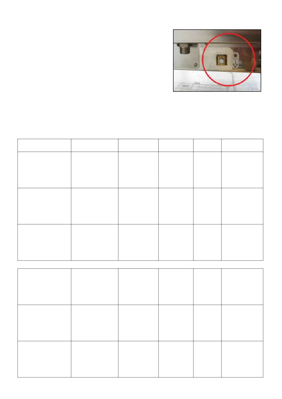
The eectiveness of the equipotential system of which the appliance is
part of, must conform to current standards.
Connect using the screw you nd in the back side of the oven, marked
with the word EQUIPOTENTIAL.
The Manufacturer declines all and every responsibility if this important
accident prevention norm is not complied with. If the feeding cable is
damaged, it must be replaced by the technical service or in any case
by similar qualied personnel, in order to avoid any risk.
1.7 TECHNICAL DATA FOR ELECTRICAL CONNECTION
Model
Power loading
and voltage
no. and motor
power
Heating
power
Absorbed
current
Feed cable
section
4 x 1/1 GN- 60x40
Electric
5 x 1/1 GN- 60x40
Electric
6.5 kW
380 - 415 V 3N~
50 Hz Analog
50/60 Hz Touch
2 x 240 W 6.0 kW 10.0 A 5 x 2.5 mm
2
6 x 1/1 GN- 60x40
Electric
7 x 1/1 GN- 60x40
Electric
11.6 kW
380 - 415 V 3N~
50 Hz Analog
50/60 Hz Touch
2 x 240 W 11.0 kW 18.0 A 5 x 4.0 mm
2
10 x 1/1 GN- 60x40
Electric
12 x 1/1 GN- 60x40
Electric
17.3 kW
380 - 415 V 3N~
50 Hz Analog
50/60 Hz Touch
3 x 240 W 16.5 kW 26.0 A 5 x 6.0 mm
2
4 x 1/1 GN- 60x40
Gas
5 x 1/1 GN- 60x40
Gas
0.3 kW
220 - 240 V 1N~
50 Hz Analog
50 Hz Touch
1 x 240 W -- 1.2 A 3 x 1.5 mm
2
6 x 1/1 GN- 60x40
Gas
7 x 1/1 GN- 60x40
Gas
0.3 kW
220 - 240 V 1N~
50 Hz Analog
50 Hz Touch
1 x 240 W -- 1.2 A 3 x 1.5 mm
2
10 x 1/1 GN- 60x40
Gas
12 x 1/1 GN- 60x40
Gas
0.6 kW
220 - 240 V 1N~
50 Hz Analog
50 Hz Touch
2 x 240 W -- 2.4 A 3 x 1.5 mm
2
EN