I340 GB 06 16
21
G
B
ALARMS
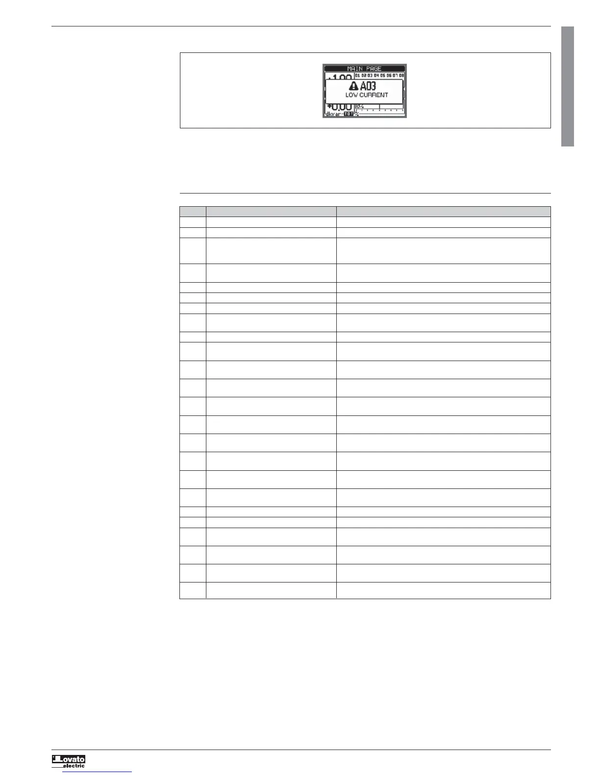
– When an alarm is generated, the display will show an alarm icon, the code and the description of the alarm in the language selected.
– If the navigation keys in the pages are pressed, the pop-up window showing the alarm indications will momentarily disappear and reappear again after a few
seconds.
– The red LED near the alarm icon on the front panel is flashing when an alarm is active.
–
If enabled, the local and remote alarm buzzers are activated.
– Alarms can be cleared by pressing .
– If the alarm cannot be cleared, the condition that generated the alarm must still be solved.
– If one or more alarms occur, the behaviour of the DCRG8/DCRG8IND will depend on the active alarm property setting.
ALARM PROPERTIES
Various properties can be assigned to each alarm, including user alarms (User Alarms, UAx):
– Enabled - General enabling of the alarm. If the alarm is not enabled, it is not considered,
– Retentive – Memory remains latched even if the cause of the alarm has been eliminated.
– Operating mode – Operating modes in which the alarm is enabled.
– Global alarm 1 -2 -3 - Activates the output assigned to this function.
– Step disconnection mode – Defines whether and how the capacitor steps must be disconnected when the alarm is present. OFF = no disconnection;
SLOW = gradual disconnection; FAST = Immediate disconnection.
– Slave disconnection mode – Defines, for Master-Slave applications when this alarm arises, if the disconnection is extended to all the steps of the system
(GENERAL) or only to the output of the interested panel (LOCAL).
– Inhibition - The alarm can be temporarily disabled by activating an input that can be programmed with the Inhibit function.
– Modem call – The alarm will be signalled remotely by sending a modem call under the conditions and modality defined in modem parameters.
– No LCD - The alarm is managed normally, but not shown on the display.
– Delay time – Time delay in minutes or seconds before the alarm is generated.
ALARM DESCRIPTION
CODE ALARM DESCRIPTION
A01 Undercompensation All the available steps are connected but the cosphi is still more inductive than the setpoint.
A02 Overcompensation All the steps are disconnected but the cosphi is still more capacitive than the setpoint.
A03 Current too low The current flowing in the current inputs is lower than minimum value of measurement
range.
This condition can occur normally if the plant has no load.
A04 Current too high The current flowing in the current inputs is higher than the maximum of measurement
range.
A05 Voltage too low The measured voltage is lower than the threshold set with P17.14.
A06 Voltage too high The measured voltage is higher than the threshold set with P17.13.
A07 Panel temperature too high The panel temperature is higher than threshold set with P17.06.
A08 Capacitor current overload The calculated capacitor current overload is higher than threshold set with P17.08 and/or
P17.09.
A09 No-Voltage release A no-voltage release has occurred on the line voltage inputs for more than 8ms.
A10 Step xx failure The residual power percentage of the step xx is lower than minimum threshold set with
P17.12.
A11 Harmonic protection module no. n The RMS current measured by harmonic protection module n is higher than threshold set
Current too high with P18.n.06.
A12 Harmonic protection module no. n The current THD measured by harmonic protection module n is higher than threshold set
I -THD too high with P18.n.07.
A13 Harmonic protection module no. n The component percentage of 5th harmonic content measured by harmonic protection
5th Harm too high module n is higher than threshold set with P18.n.08.
A14 Harmonic protection module no. n The component percentage of 7th harmonic content measured by harmonic protection
7th Harm too high module n is higher than threshold set with P18.n.09.
A15 Harmonic protection module no. n The component percentage of 11th harmonic content measured by harmonic protection
11th Harm too high module n is higher than threshold set with P18.n.10.
A16 Harmonic protection module no. n The component percentage of 13th harmonic content measured by harmonic protection
13th Harm too high module n is higher than threshold set with P18.n.11.
A17 Harmonic protection module no. n The measurement of temperature 1 input on harmonic protection module n is higher than
Temperature 1 too high threshold set with P18.n.12.
A18 Harmonic protection module no. n The measurement of temperature 2 input on harmonic protection module n is higher
Temperature 2 too high than threshold set with P18.n.13.
A19 Slave xx link error The slave no. x does not communicate with the master. Problem with the RS485 wiring.
UAx User alarm x (x=1..8) User-defined alarm, as specified by parameters of menu M25.
A20 Maintenance interval 1 elapsed The maintenance 1 interval hours are elapsed. After maintenance service, reset counter
with command C16.
A21 Maintenance interval 2 elapsed The maintenance 2 interval hours are elapsed. After maintenance service, reset counter
with command C17.
A22 Maintenance interval 3 elapsed The maintenance 3 interval hours are elapsed. After maintenance service, reset counter
with command C18.
A25 Maintenance interval 4 elapsed The maintenance 4 interval hours are elapsed. After maintenance service, reset counter
with command C19.
 Loading...