I340 GB 06 16
G
B
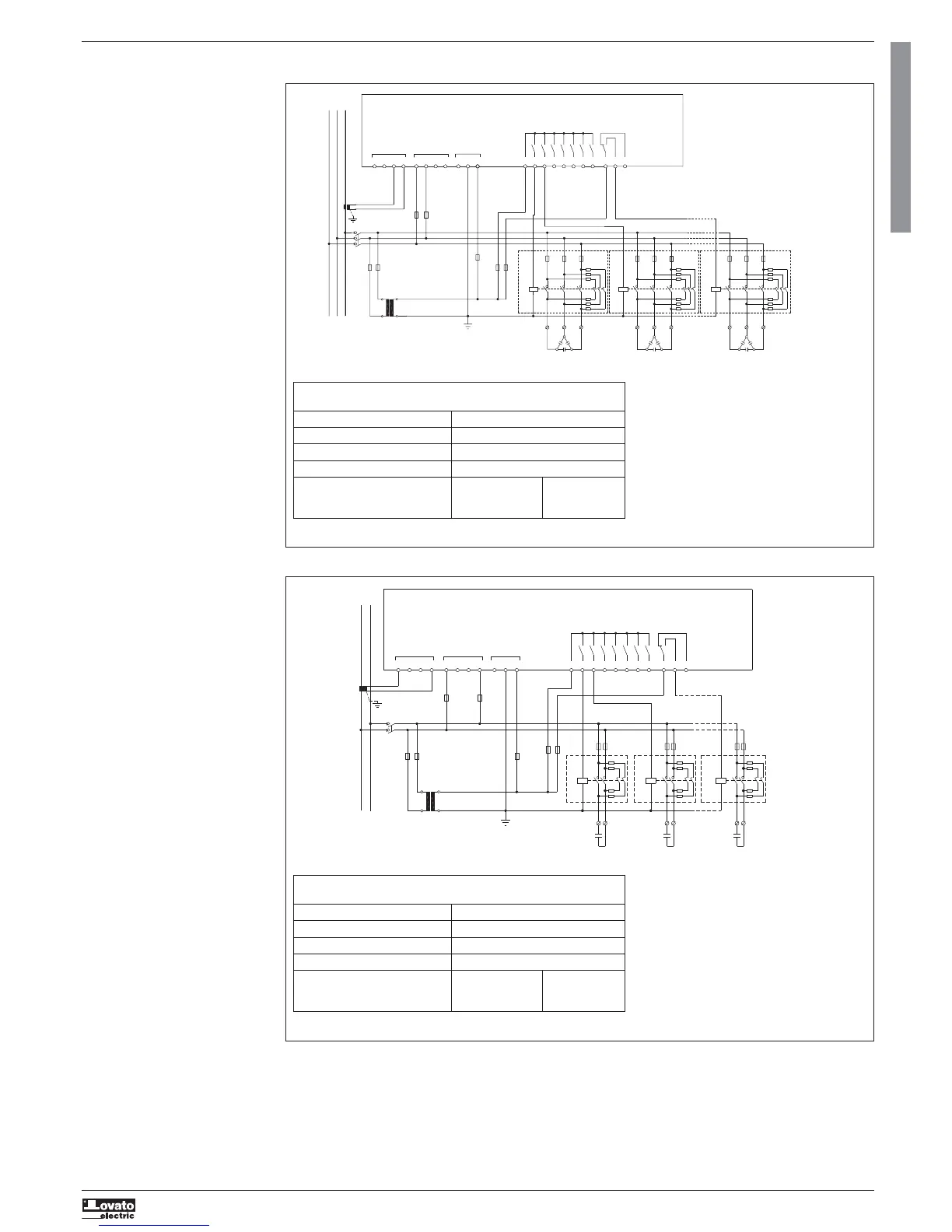
WIRING DIAGRAMS
Standard three-phase installation
MAINS
L1 L2 L3
DCRG8/DCRG8IND
CURRENT
1/5A~
AUX
SUPPLY
110-415V~
110-250V=
1
23
4
56
7
8910
11
1
23
4
56
7
8
OUT
19 20
21 2212 13 14 15 16 17 18
I1 I2 I3
C
L1 L2 L3 N
nc
A1 A2
S1
S2
CT1
FU9
QS1
FU13
TC1
FU10
FU11
FU12
FU1
KM1
R
R
KM2
R
R
FU2
KM8
FU8
R
R
K1 K2
K8
LOAD
Contattori BFK...
BFK... contactors
INPUT
VOLTAGE
100-600V~
THREE-PHASE CONNECTION (default)
Default wiring configuration for standard applications
Voltage measurement 1 ph-to-ph voltage reading L1-L2
Current measurement L3 phase
Phase angle offset Between V (L1-L2 ) and I (L3) 90°
Capacitor overload measurement 1 reading calculated on L1-L2
Parameter setting P02.03 = Three-phase P02.22 = LV
P02.04 = L3
P02.06 = L1-L2
Single-phase installation
NOTE: Recommended fuses for aux supply and voltage measurement inputs: F1A (fast).
NOTE: Recommended fuses for aux supply and voltage measurement inputs: F1A (fast).
MAINS
LN
DCRG8/DCRG8IND
CURRENT
1/5A~
INPUT
VOLTAGE
100-600V~
AUX
SUPPLY
110-415V~
110-250V=
1
23
4
56
7
8
OUT
19 20
21 2212 13 14 15 16 17 18
I1 I2 I3
C
L1 L2 L3 N
nc
A1 A2
Contattori BFK...
BFK... contactors
1
23
4
56
7
8910
11
S1
S2
QS1
CT1
LOAD
FU13
TC1
FU9
FU10
FU11
FU12
FU1
FU2
FU8
KM1
KM2
KM8
RRR
K1 K2
K8
SINGLE-PHASE CONNECTION
Wiring configuration for single-phase applications
Voltage measurement 1 phase voltage reading L1-N
Current measurement L1 phase
Phase angle offset Between V (L1-N ) and I (L1) 0°
Capacitor overload measurement 1 reading calculated on L1-N
Parameter setting P02.03 = Single-phase P02.22 = LV
P02.04 = L1
P02.06 = L1-N
25
 Loading...