Doc: MHIT101A1012.doc 01/08/2013 p. 1 / 38
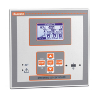
RGK600 RGK600
RGK600SA RGK600SA
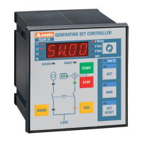
Unità di controllo Generating set
per gruppi elettrogeni controller
MANUALE OPERATIVO INSTRUCTIONS MANUAL
Prima di qualsiasi intervento sullo strumento, togliere tensione dagli ingressi di misura e di
alimentazione e cortocircuitare i trasformatori di corrente.
Il costruttore non si assume responsabilità in merito alla sicurezza elettrica in caso di utilizzo
improprio del dispositivo.
I prodotti descritti in questo documento sono suscettibili in qualsiasi momento di evoluzioni o
di modifiche. Le descrizioni ed i dati a catalogo non possono pertanto avere alcun valore
contrattuale.
Un interruttore o disgiuntore va compreso nell’impianto elettrico dell’edificio. Esso deve
trovarsi in stretta vicinanza dell’apparecchio ed essere facilmente raggiungibile da parte
dell’operatore. Deve essere marchiato come il dispositivo di interruzione dell’apparecchio: IEC/
EN 61010-1 § 6.12.2.1.
Pulire lo strumento con panno morbido, non usare prodotti abrasivi, detergenti liquidi o
solventi.
Before any maintenance operation on the device, remove all the voltages from measuring
and supply inputs and short-circuit the CT input terminals.
Products illustrated herein are subject to alteration and changes without prior notice.
Technical data and descriptions in the documentation are accurate, to the best of our
knowledge, but no liabilities for errors, omissions or contingencies arising there from are
accepted.
A circuit breaker must be included in the electrical installation of the building. It must be
installed close by the equipment and within easy reach of the operator.
It must be marked as the disconnecting device of the equipment:
IEC /EN 61010-1 § 6.12.2.1.
Clean the instrument with a soft dry cloth; do not use abrasives, liquid detergents or
solvents
.
Indice Pagina
Introduzione 2
Descrizione 2
Funzione dei tasti frontali 3
LED frontali 3
Modi operativi 3
Messa in tensione 3
Menu principale 4
ccesso tramite password 4
Tabella delle pagine del display 5
Sensori resistivi carburante, temperatura, pressione
7
Start remoto su vesrioni ..SA
8
Ingressi, uscite, variabili interne, contatori 8
Soglie limite (LIMx) 8
Variabili da remoto (REMx) 9
llarmi utente (UAx) 9
Test automatico 10
Modo sleep 10
CAN bus 10
Porta di programmazione IR 12
Impostazione parametri da PC 12
Impostazione parametri da pannello frontale 13
Tabella dei parametri 14
llarmi 25
Proprietà degli allarmi 25
Tabella allarmi 26
Descrizione degli allarmi 28
Tabella funzioni ingressi 30
Tabella funzioni uscite 31
Menu comandi 32
Installazione 33
Schemi di connessione 34
Disposizione morsetti 36
Dimensioni meccaniche e foratura pannello 36
Caratteristiche tecniche 37
Cronologia revisioni manuale 38
Index Page
Introduction 2
Description 2
Front buttons functions 3
Front LED indication 3
Operating modes 3
Power-up 3
Main menu 4
Password access 4
Table of display pages 5
Resistive sensors for fuel, temperature and pressure
7
Remote start for …SA versions
8
Inputs, outputs, internal variables, counters 8
Limit thresholds (LIMx) 8
Remote-controlled variables (REMx) 9
User alarms (UAx) 9
utomatic test 10
Sleep mode 10
CAN bus 10
IR programming port 12
Parameter setting via PC 12
Parameters setting (setup) from front panel 13
Parameter table 14
larms 25
larm properties 25
larm table 26
larm description 28
Input function table 30
Output function table 31
Command menu 32
Installation 33
Wiring diagrams 34
Terminal position 36
Mechanical dimensions and panel cutout 36
Technical characteristics 37
Manual revision history 38
ATTENZIONE!!
Leggere attentamente il manuale prima dell’utilizzo e l’installazione.
Questi apparecchi devono essere installati da personale qualificato, nel
rispetto delle vigenti normative impiantistiche, allo scopo di evitare danni a
persone o cose.
WARNING!
x Carefully read the manual before the installation or use.
x This equipment is to be installed by qualified personnel, complying to
current standards, to avoid damages or safety hazards.