Atom Operator Manual Appendix B
LSC Lighting Systems (Aust) Pty. Ltd. 40
16.0 APPENDIX B: ANALOGUE OUTPUT CONNECTORS
The Atom’s optional analogue outputs provide an analogue control voltage (0 to +10 or -10 volts) on a one
wire per channel basis to control analogue dimmers.
Analogue outputs are provided in modules.
The maximum number of analogue modules that may be fitted depends upon the model of the Atom.
Model Maximum number of modules
Atom 12/24 1
Atom 24/48 2
Three different types of connector are available. They are DB15, DB25 and DIN 8.
The number of channels that each module can provide depends upon the type of connectors that are fitted.
Connector type/No of pins. Connectors per module. Number of channels per
module.
DB15 2 24
DB25 1 24
DIN 8 4 24
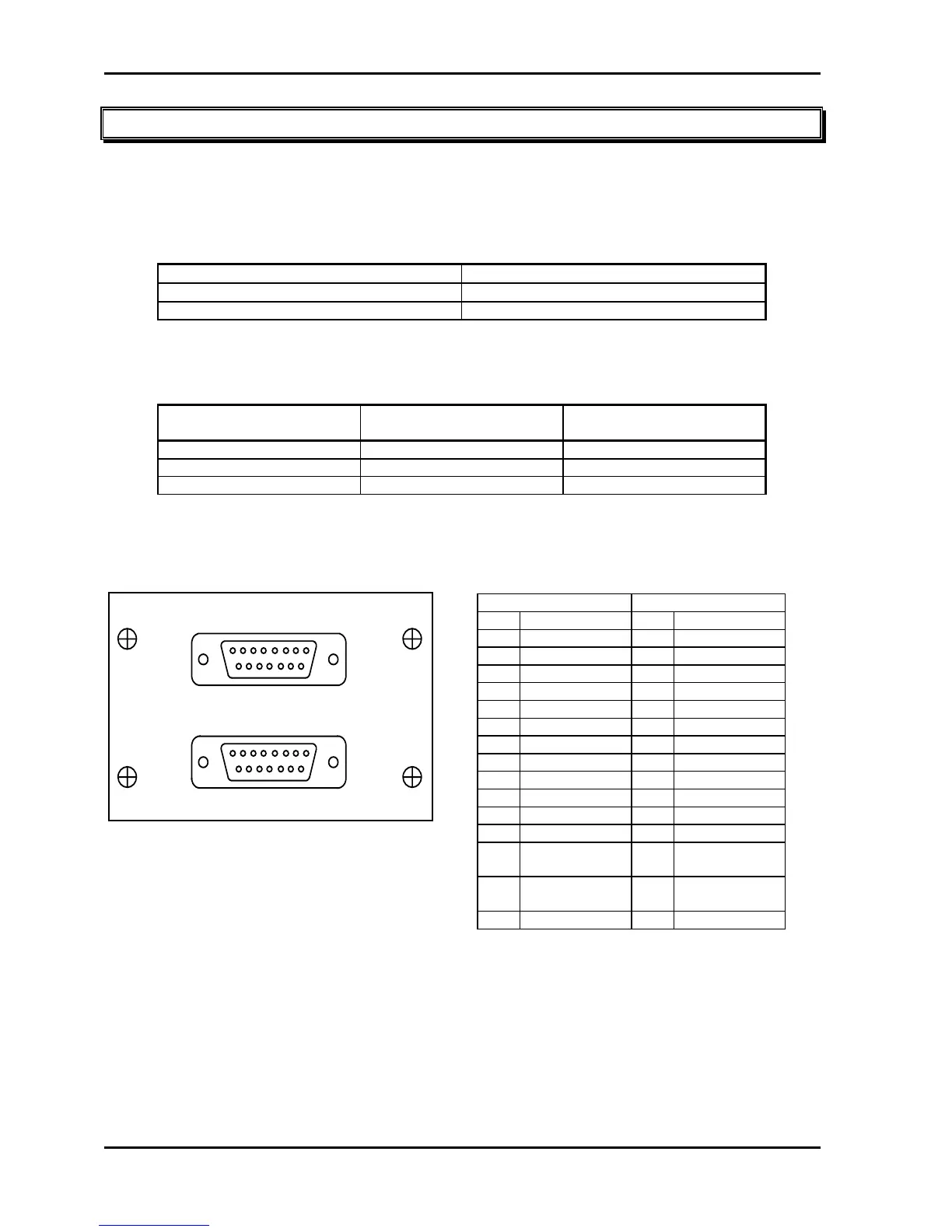
DB 15 Pinouts
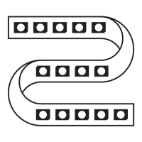
The following diagram shows one DB15 module with its two connectors as viewed from the rear of the Atom.
ANALOG OUTPUT
81234567
15 14 13 12 11 10 9
81234567
15 14 13 12 11 10 9
A
B
18
915
18
15 9
If a second DB15 connector module is fitted (to the right of the first module when viewed from the rear) its two
connectors provide outputs for channels 25 to 48. To obtain the pin connections, simply substitute channels
25 to 48 for channels 1 to 24 in the table.
Connector A Connector B
Pin Function Pin Function
1 Channel 1 1 Channel 13
2 Channel 2 2 Channel 14
3 Channel 3 3 Channel 15
4 Channel 4 4 Channel 16
5 Channel 5 5 Channel 17
6 Channel 6 6 Channel 18
7 Channel 7 7 Channel 19
8 Channel 8 8 Channel 20
9 Channel 9 9 Channel 21
10 Channel 10 10 Channel 22
11 Channel 11 11 Channel 23
12 Channel 12 12 Channel 24
13 Not
Connected
13 Not
Connected
14 Not
Connected
14 Not
Connected
15 Common 0V 15 Common 0V