Atom Operator Manual Appendix B
LSC Lighting Systems (Aust) Pty. Ltd. 41
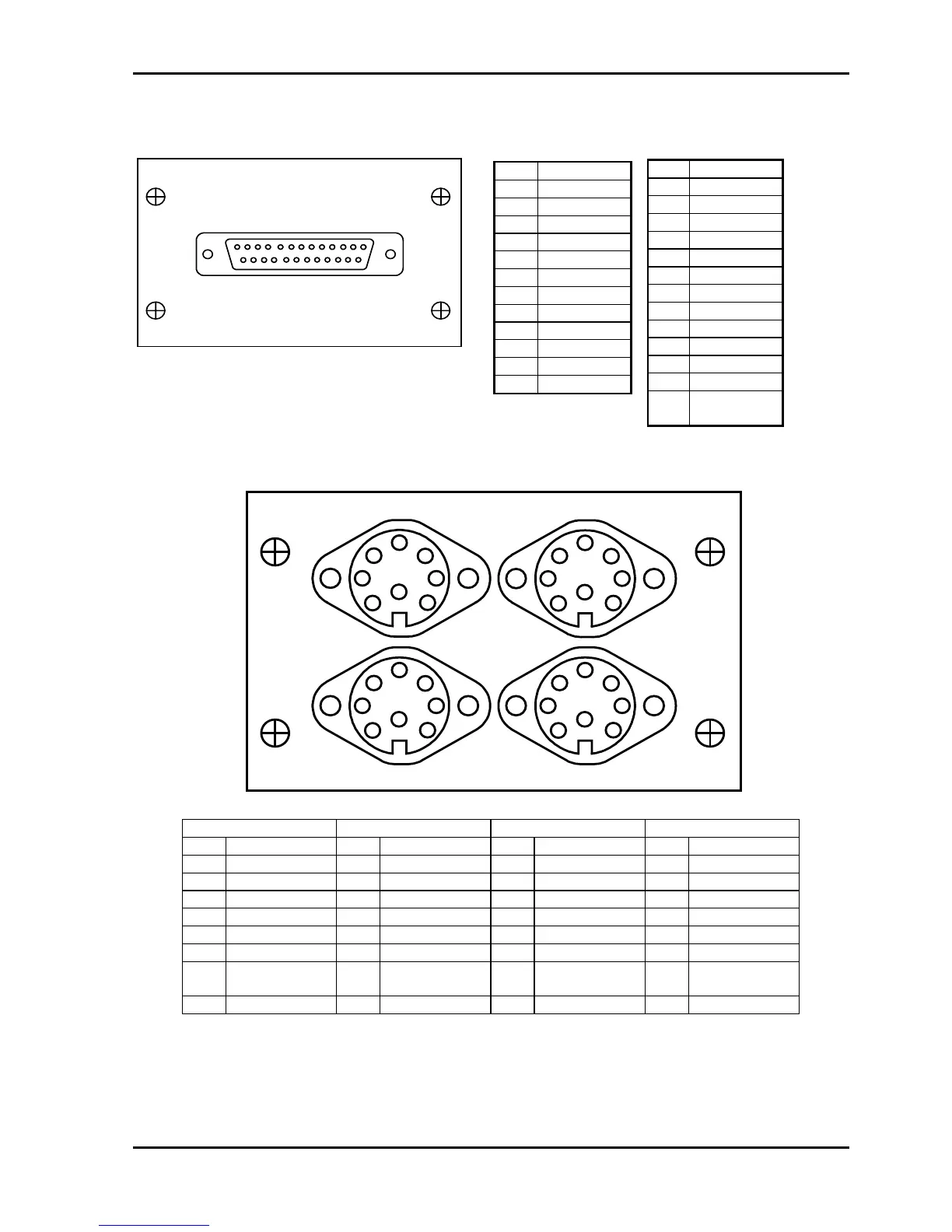
DB25 Pinouts
The following diagram shows one DB25 module with its single connector as viewed from the rear of the Atom.
ANALOG OUTPUT
14
45678 3 2910111213
1516171819202122232425
1
1
14
13
25
If a second DB25 connector module is fitted (to the
right of the first module when viewed from the rear)
it provides outputs for channels 25 to 48.
DIN 8 Pin PINOUTS
The following diagram shows one DIN 8 module with its four connectors as viewed from the rear of the Atom.
5
7
8
5
7
8
8
8
ANALOG OUTPUT
AB
CD
5
7
5
7
1
2
3
4
6
1
2
3
4
6
1
2
3
4
6
1
2
3
4
6
Connector A Connector B Connector C Connector D
Pin Function Pin Function Pin Function Pin Function
1 Channel 1 1 Channel 7 1 Channel 13 1 Channel 19
2 Channel 2 2 Channel 8 2 Channel 14 2 Channel 20
3 Channel 3 3 Channel 9 3 Channel 15 3 Channel 21
4 Channel 4 4 Channel 10 4 Channel 16 4 Channel 22
5 Channel 5 5 Channel 11 5 Channel 17 5 Channel 23
6 Channel 6 6 Channel 12 6 Channel 18 6 Channel 24
7Not
Connected
7Not
Connected
7Not
Connected
7Not
Connected
8 Common 0V 8 Common 0V 8 Common 0V 8 Common 0V
If a second DIN connector module is fitted (to the right of the first module when viewed from the rear) it
provides outputs for channels 25 to 48.
APPENDIX C “TERMINOLOGY”
Pin Function
13 Channel 13
14 Channel 14
15 Channel 15
16 Channel 16
17 Channel 17
18 Channel 18
19 Channel 19
20 Channel 20
21 Channel 21
22 Channel 22
23 Channel 23
24 Channel 24
25 Common
0V
Pin Function
1 Channel 1
2 Channel 2
3 Channel 3
4 Channel 4
5 Channel 5
6 Channel 6
7 Channel 7
8 Channel 8
9 Channel 9
10 Channel 10
11 Channel 11
12 Channel 12