LSI Corporation
- 60 -
6Gb/s MegaRAID SAS RAID Controllers User Guide
August 2012
Chapter 3: MegaRAID SAS RAID Controller Characteristics
6Gb/s MegaRAID SAS RAID Controller Family
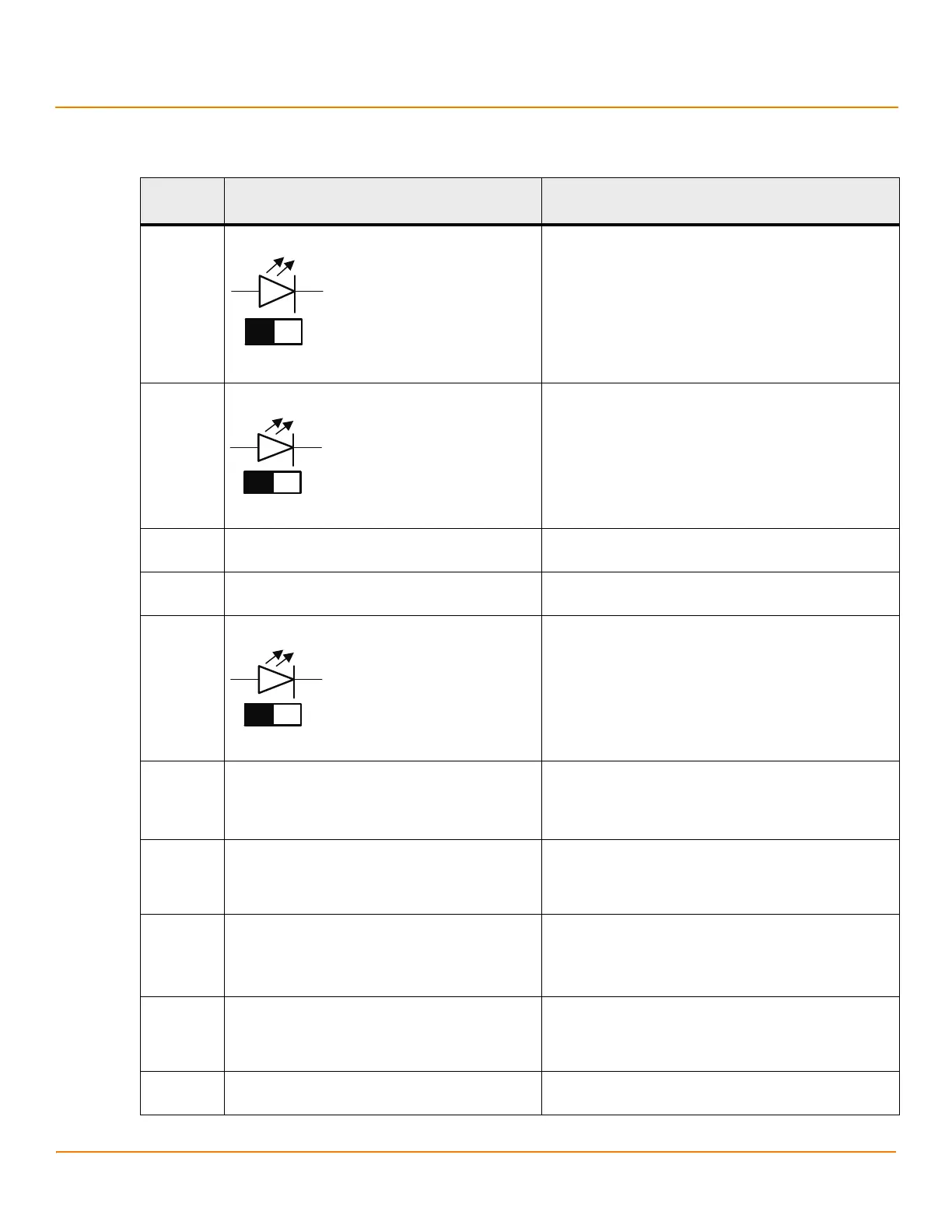
The following table describes the jumpers and the connectors on the MegaRAID SAS 9285-8e RAID controller.
Table 16 MegaRAID SAS 9285-8e RAID Controller – Connectors
Jumper/
Connector
Type Description
J1A1 Write-Pending LED header 2-pin connector
Connects to an LED that indicates when the data in the
cache has yet to be written to the storage devices. Used
when the write-back feature is enabled.
J1A2 Global Drive Fault LED header 2-pin connector
Connects to an LED that indicates whether a drive is in a
fault condition.
J1A3 x4 SAS Ports 4 to 7 External connector SFF-8088 x4 external mini SAS connector
Connects the controller by cable to SAS drives or SATA drives.
J1B1 x4 SAS Ports 0 to 3 External connector SFF-8088 x4 external mini SAS connector
Connects the controller by cable to SAS drives or SATA drives.
J2A1 Activity LED header 2-pin connector
Connects to an LED that indicates activity on the drives
connected to the controller.
J2A2
I
2
O Mode jumper
2-pin connector
Installing this jumper causes the RAID controller to run in I
2
0
mode. The default mode of operation is without the shunt
and running in Fusion mode.
J2A3 Advanced Software Options Hardware Key header 3-pin header
Enables support for the Advanced Software Options
features, which include CacheCade, FastPath, Recovery, and
SafeStore disk encryption.
J2B1 Standard Edge Card connector The RAID controller interfaces with the host system though a
standard edge card.
This interface provides power to the board and an I
2
C
interface connected to the I
2
C bus for IPMI.
J4A1 Serial EEPROM 2-pin connector
Provides controller information, such as the serial number,
revision, and manufacturing date. The default is no
shunt installed.
J4A2 LSI Test header 2-pin connector
Reserved for LSI use.
 Loading...