Chapter 5 Positioning Instructions
5 - 1
Chapter 5 Positioning Instructions
This chapter describes the definitions, functions, use of the positioning instructions used in XGB
positioning functions and the program examples.
5.1 Positioning Instruction Alarm
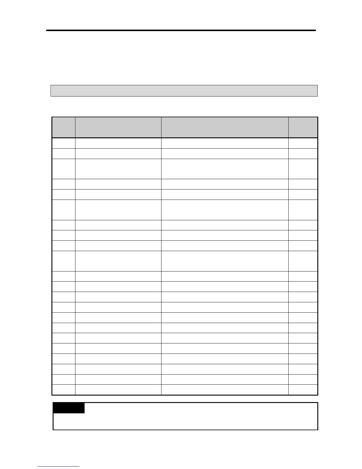
The positioning instructions used for XGB positioning are as follows.
(1) In case of XBC/XBM
Instructi
Description Conditions Remark
Start return to the origin
DST
Direct starting
Slot, instruction axis, position, speed, dwell time,
Slot, instruction axis, step number
Linear interpolation starting
Slot, instruction axis, step number, axis information
SST
Simultaneous starting
Slot, instruction axis, axis X step, axis Y step,
axis Z step, axis information
Slot, instruction axis, deceleration time
SSP
Position synchronization
Slot, instruction axis, step number, main axis position,
Slot, instruction axis, synchronization rate, delay time
Slot, instruction axis, position
Slot, instruction axis, speed
Positioning speed override
Slot, instruction axis, position, speed
Slot, instruction axis, inching amount
Change starting step number
Slot, instruction axis, step number
Slot, instruction axis, position
Reset error, cancel output inhibition
Slot, instruction axis, inhibit/allow pulse output
Save parameter/operation data
Slot, instruction axis, select the storage area
Slot, instruction axis, output cycle, off duty rate
• XGB positioning instructions are activated at the rising edge. That is, when the execution contact point
is On, it carried out the instruction only once.