MCS640 Thermal Imager Manual Introduction • 10
• Housings and enclosure options, matched to the harsh environment (explosive, hazardous, outdoor,
etc.)
• Communication cable and power supply
• Start-up support
LumaSense engineering staff and sales consultants follow a system approach to online thermal processing
control. They have specific expertise and technical skills required to specify and integrate the appropriate
application-specific imaging components with your existing control platform. LumaSense takes the ultimate
responsibility for the thermal imaging system meeting your design specifications and saving you time, cost,
and allocation of in-house resources.
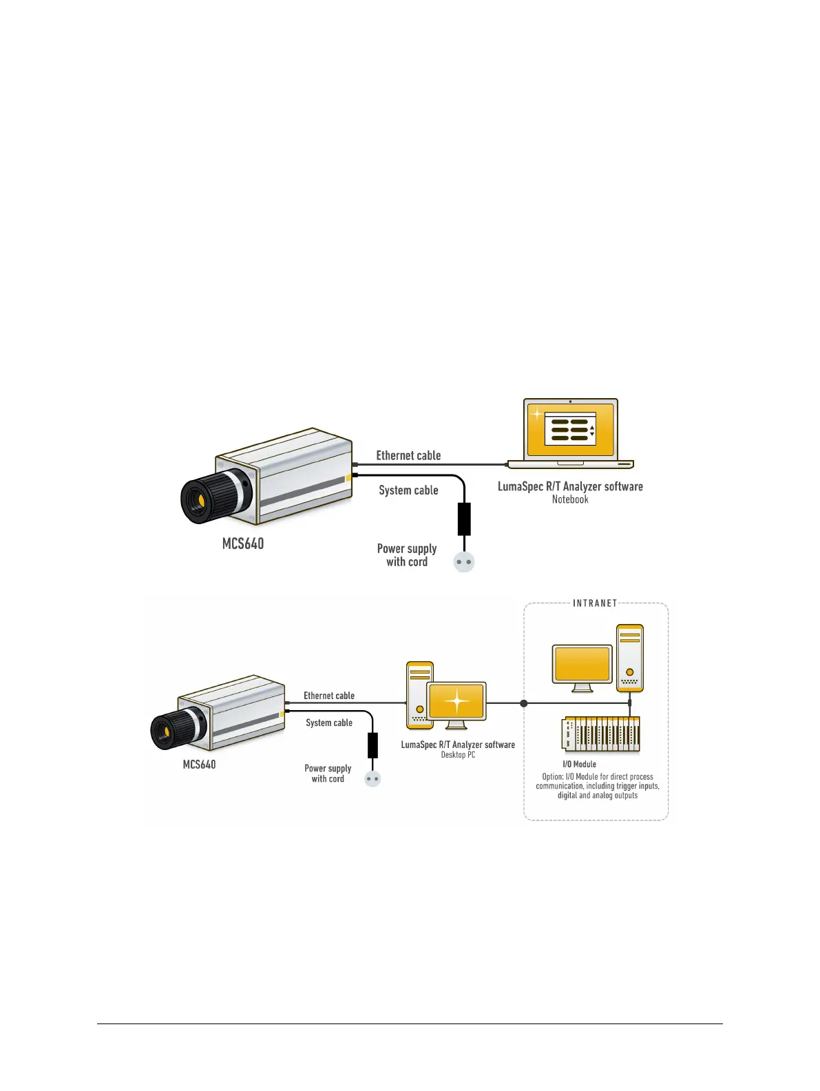
2.1.2 System Configuration
LumaSense’s thermal imagers offer several configuration options. The system can be set up by connecting the
camera to a network device (switch) or by connecting the camera directly to a dedicated computer using a
cross-over Ethernet cable. Additionally, the camera can be used with a desktop PC or with a notebook PC for a
mobile measuring system.
2.2 Scope of Delivery
2 m Ethernet cable, 2 m power supply cable, power supply unit (100 to 240 VAC, 47 to 63 Hz), mounting
adapter, lens cap, carrying case, quick start guide, and LumaSpec R/T Viewer software.