MCS640 Thermal Imager Manual Introduction • 12
Power supply and digital interface are galvanically isolated from each
other
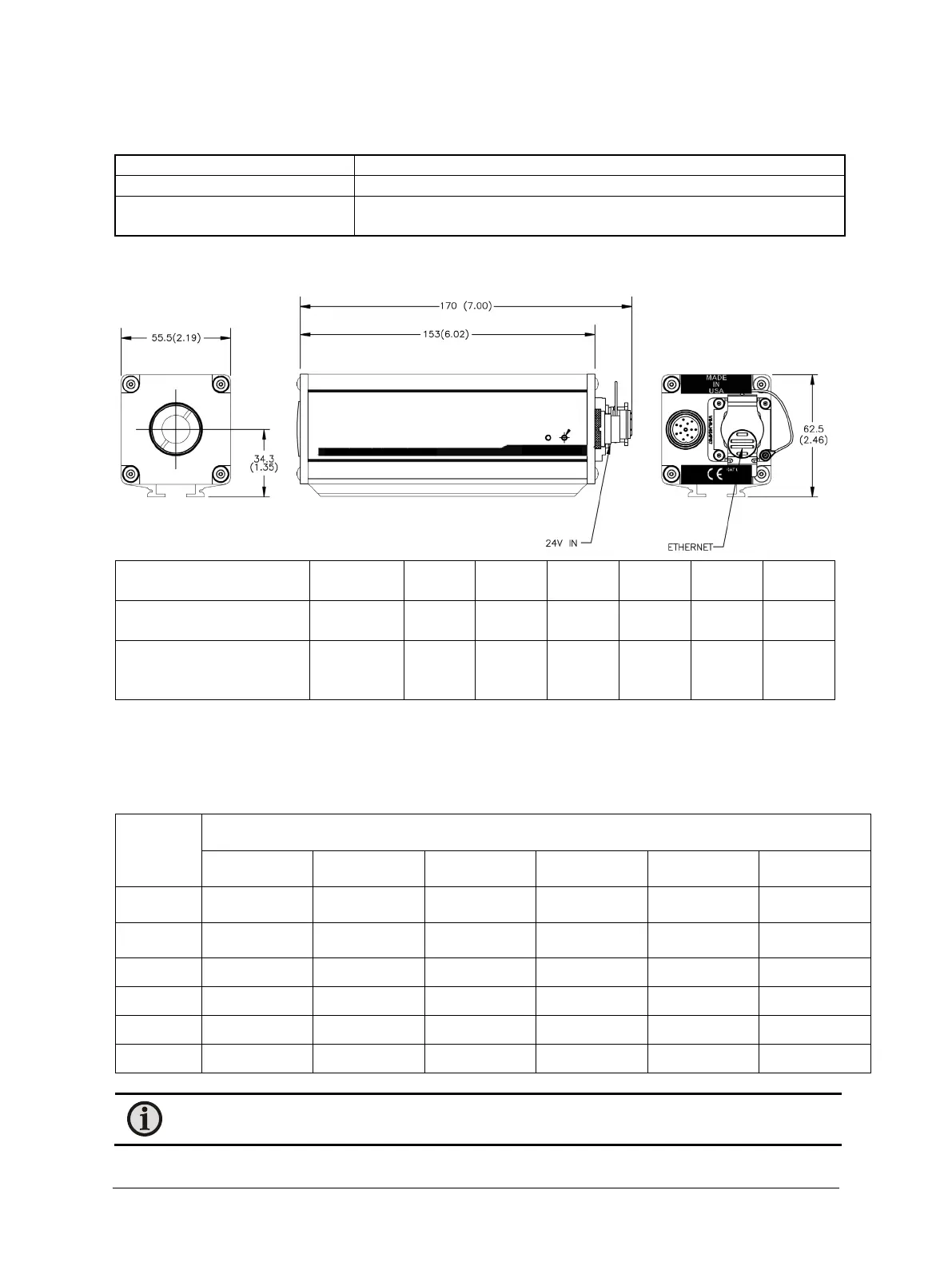
2.4 Dimensions
Filter code I5 (without
filter adaptor)
Filter code I1, I2, I3, I4, I8
and V (including filter
mm
mm
mm
mm
mm
mm
2.5 Optics
A wide range of alternative lenses are available for the MCS640, making the thermal imager suitable for most
applications. The table and picture below show the correlation between the measurement distance, different
optics, and the size of the measurement fields.
Distance of
object [m]
Measurement field W x H [m]
3.5° x 2.6° 5.4° x 4.0° 10.8° x 8.1° 22.5° x 17.0° 33.3° x 25.3° 40.4° x 30.9°
0.30 - - - - - -
0.60 - - - - - -
1.00 0.06 x 0.05 0.19 x 0.14 0.19 x 0.14 0.40 x 0.30 0.60 x 0.45 0.74 x 0.55
1.50 0.09 x 0.07 0.14 x 0.10 0.28 x 0.21 0.60 x 0.45 0.90 x 0.67 1.10 x 0.83
2.50 0.15 x 0.11 0.24 x 0.17 0.47 x 0.35 0.99 x 0.75 1.50 x 1.12 1.84 x 1.38
10.00 0.61 x 0.45 0.94 x 0.70 1.91 x 1.43 3.98 x 2.99 5.98 x 4.99 7.36 x 5.53
Note: Distances in the table may not apply to some high-temperature situations. Be sure to consult
the Applications Department to determine the proper distance for your application.