Do you have a question about the Lumiax Magic Series and is the answer not in the manual?
Detailed safety warnings and essential precautions for operating the solar controller.
Manufacturer's disclaimer regarding damages and liabilities under specific conditions.
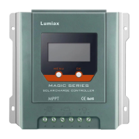
Highlights the advanced features and capabilities of the Magic series MPPT solar controller.
Explains MPPT technology for efficient solar conversion and the concept of current boost.
Explains benefits of high voltage strings and grid-tie modules with MPPT technology.
Compares MPPT controller advantages over traditional controllers, highlighting energy efficiency.
Discusses environmental factors and conditions that can limit the effectiveness of MPPT technology.
Details the four-stage battery charging algorithm: MPPT, Boost, Float, and Equalization.
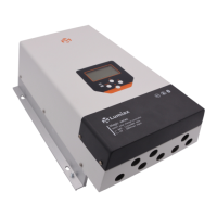
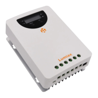
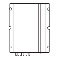
Provides detailed physical dimensions and graphical representations of the solar controller.
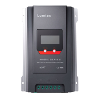
Details the physical components, connections, and interfaces of the solar controller.
Lists the accessories that are included with the solar charge controller package.
Lists optional accessories that can be purchased separately for enhanced functionality.
Explains the battery voltage sensor, load control relay, and utility/generator relay functionality.
Describes the multi-functional AUX port, its default function, and customization options.
Details the RS485 interface, including pin definitions and communication capabilities.
Information on the optional remote temperature sensor for accurate battery temperature compensation.
Details about the optional IoT module for remote monitoring and control.
Provides essential notes, precautions, and guidelines for the safe and proper installation of the controller.
Details the requirements for battery cables, including sizing, and the importance of a battery fuse.
Guidance on selecting appropriate PV cables based on array voltage, current, and cable length.
Discusses PV array sizing relative to controller power and risks of oversizing.
Guides on selecting an appropriate installation location considering heat dissipation and environment.
Instructions for preparing cables, connecting the battery, and installing fuses.
Details connecting the battery sensor, grounding, and solar module cables.
Instructions for connecting accessories and powering up the controller.
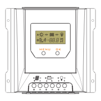
Explains the status indication provided by the green (PV Panel) and yellow (Battery) LEDs.
Details the function of each key (MENU, OK, navigation arrows) on the controller's interface.
Explains the information displayed on the LCD, including date, time, communication, PV power, and battery voltage.
Shows the static display information available on the controller, such as battery and PV parameters.
Overview of system settings, including language, time, communication mode, and backlight.
Details battery settings such as type, voltage, LVD, LVR, equalization, boost, and float voltages.
Information on accessing logged data for total energy input and battery voltage.
Displays controller information, including product name and software/hardware versions.
Instructions for configuring system settings like language, date/time, and LCD backlight.
Configuration options for communication modes, device ID, diesel generator maintenance, and AUX port.
Procedures for factory resetting the controller, including data and BLE password clearing.
Configuring battery type (GEL, AGM, LIQ) and system voltage (12V, 24V, 48V, AUTO).
Setting Low Voltage Disconnect (LVD) and Low Voltage Reconnect (LVR) parameters.
Adjusting equalization, boost, and float voltages for optimal battery charging stages.
Accessing graphical overview of energy input in Wh/KWh for the last 24 hours.
Displaying historical battery voltage data, including minimum and maximum values.
Configuration for 0°C charging behavior and setting charging target voltage (CVT) and recovery voltage (CVR).
Graphical overviews of energy input in Wh/KWh for the last 30 days, 360 days, and 5 years.
Records of minimum and maximum battery voltage for each day over the last 60 days.
Details the various protection mechanisms implemented in the controller, such as over current and over voltage.
Guides on identifying and resolving common faults and errors encountered with the controller.
Recommended inspection and maintenance tasks for ensuring optimal performance and longevity.
Comprehensive list of electrical specifications, including current, voltage, power, and efficiency ratings.
Physical specifications of the controller, including dimensions, weight, and terminal sizes.
Operating and storage environmental conditions, including temperature, humidity, and altitude limits.
| Brand | Lumiax |
|---|---|
| Model | Magic Series |
| Category | Controller |
| Language | English |