11|Page
Step 11: Always hold UV lamps by their ceramic ends, not by the lamp quartz. Remove the lamp
from its packaging. Again, the use of coon gloves is recommended. Remove the lamp key from
the lamp’s connector and set it aside for the next step. Be careful to not touch the key’s exposed
contacts. Insert the UV lamp into the reactor, being careful not to drop it.
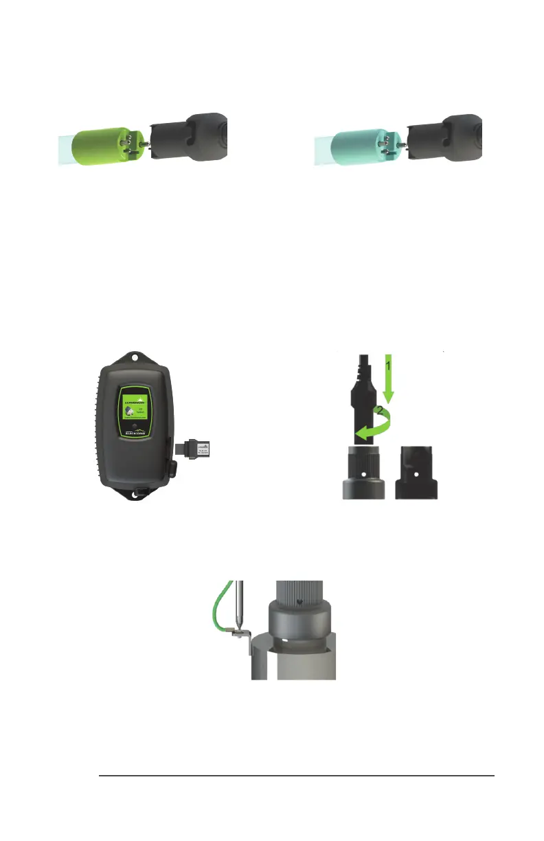
Step 12: Install the lamp key into the controller (BLACKCOMB
5.1
, BLACKCOMB
6.1
systems only).
The key always comes packaged with the lamp and sits on the connector. With the key removed
from the lamp, orient it so the label is upright and facing you. The key will plug into the lamp key
port on the right side of the controller (Figure 8).
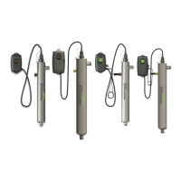
Step 13: Plug the LUMI-Loc™ lamp connector into the lamp. Note the keying for proper align-
ment (see Figure 7a, 7b). Insert the lamp connector into the gland nut and turn the connector
approximately ¼ turn to lock the connector to the gland nut as in Figure 9.
Figure 8. Lamp Key Installaon Figure 9. LUMI-Loc™ Connector
Step 14: Tighten the capve ground screw to the ground lug on the UV reactor to ensure proper
grounding.
Figure 10. Ground Screw Connecon
Step 15: Your system is now ready to be plugged into the appropriate GFCI protected outlet.
Refer to the following secon before any water is allowed to ow through the system.
Figure 7a. Standard Output UV
Lamp Connecon
Figure 7b. High Output UV
Lamp Connecon
 Loading...