2-6
CDA3000 Operation Manual
2 Mechanical installation
.
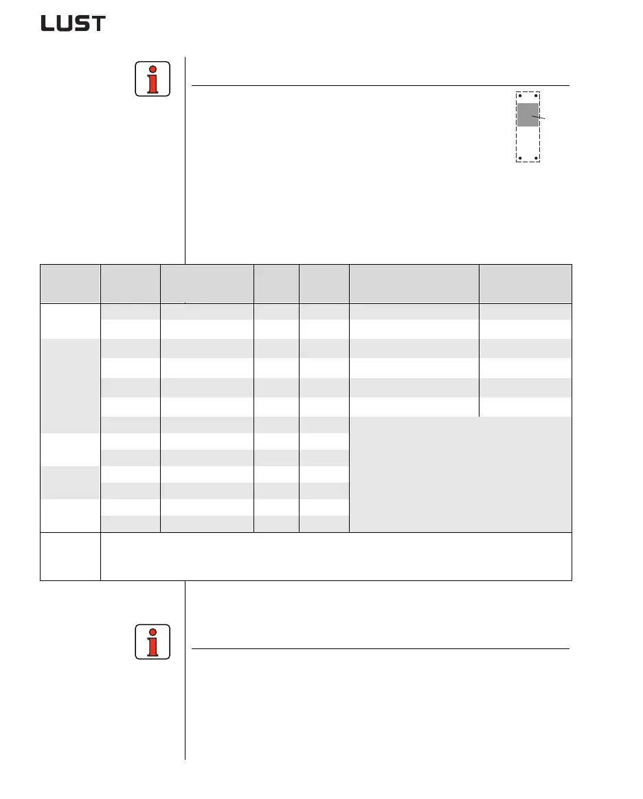
Note the following points:
• The cooling can be attained either by a sufficiently
large backing plate (see Table 2.4) or by an additional
cooler. The cooler must be mounted centrally behind
the hottest area (1) of the device.
• The temperature on the rear panel of the inverter mod-
ule must not exceed 85.0 °C. At a temperature > 85° C
the device shuts down automatically. It can only be restarted when it
has cooled.
• Required evenness of contact surface = 0.05 mm, maximum
roughness of contact surface = roughness factor 6.3
(1)
Size Output Inverter module
PV
1)
[W]
RthK
3)
[K/W]
Backing plate (unvarnished
steel min. cooling area
Ambient
temperature
BG1
0.375 kW CDA32.003,Cx.x 25 W 0.05 None 45°C
0.75 kW
CDA32.004,Cx.x 45 W 0.05 650x100mm = 0.065m²
45°C
1)
, 40°C
2)
BG2
1.1 kW CDA32.006,Cx.x 75 W 0.05 650x460mm = 0.3m²
45°C
1)
, 40°C
2)
1.5 kW CDA32.008,Cx.x 95 W 0.05 650x460mm = 0.3m²
45°C
1)
, 40°C
2)
0.75 kW CDA34.003,Cx.x 45 W 0.05 None
45°C
1)
, 40°C
2)
1.5 kW CDA34.005,Cx.x 80 W 0.05 650x460mm = 0.3m²
45°C
1)
, 40°C
2)
2.2 kW CDA34.006,Cx.x 100 W 0.05
An additional cooler is required to supply
adequate cooling.
For project planning notes see Appendix A.3.
BG3
3.0 kW CDA34.008,Cx.x 150 W 0.03
4.0 kW CDA34.010,Cx.x 190 W 0.03
BG4
5.5 kW CDA34.014,Cx.x 220 W 0.02
7.5 kW CDA34.017,Cx.x 270 W 0.02
BG5
11 kW
CDA34.024,Cx.x 400 W 0.015
15 kW CDA34.032,Cx.x 480 W 0.015
1) With a power stage clock frequency of 4 kHz
2) With a power stage clock frequency of 8 kHz
3) Thermal resistance between active cooling area and cooler
Table 2.4 Required cooling with cold plate
Note the following points:
• The backing plate must be grounded over a large area.
• The best result for effective EMC installation is attained with a chro-
mated or galvanized backing plate. If backing plates are varnished,
the coating must be removed in the area of the contact surface!