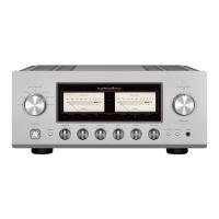
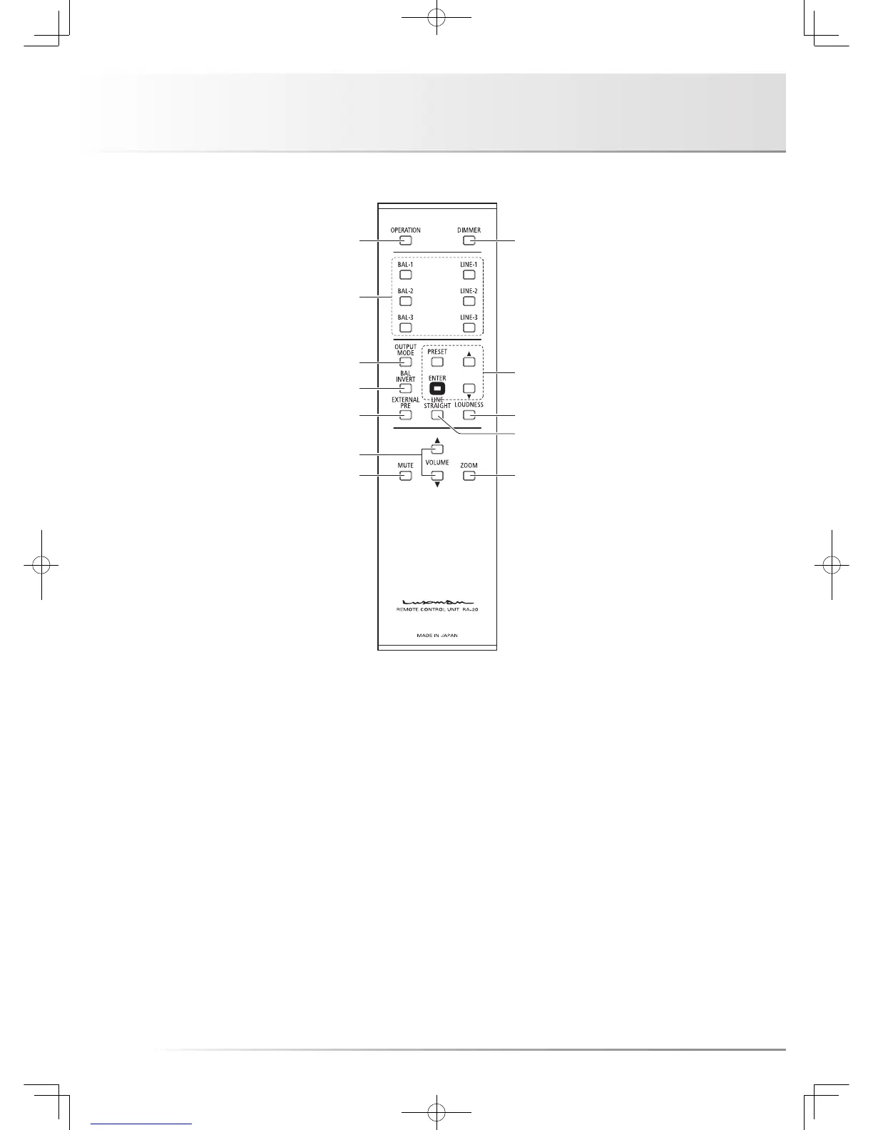
1. Operation switch (OPERATION)
Turns this unit from the standby state to operation state.
When the main power switch on the rear panel is turned on
to set this unit to the standby state and this switch is turned
on, this unit is set to the operation state.
2. Input selector
(LINE-1, LINE-2, LINE-3, BAL-1, BAL-2,
BAL-3)
Selects the unbalanced input terminal or balanced input ter-
minal, both of which are located on the rear panel.
The input/output muting circuit is activated to mute sound
during selecting an input.
 Loading...