R FR 5018 Reference Manual. Rev 1.0
Page 12 of 24
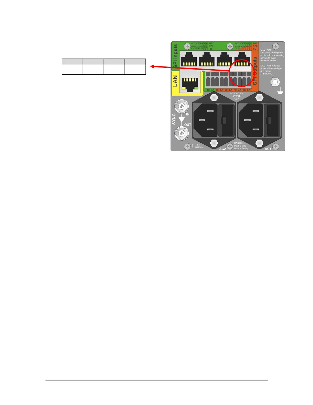
Alarm Connection
An external alarm connection is available
from the rack frame.
Function and connection information is
described below.
Alarm Function
The user can assign triggers for the
preferred Major / Minor and No Alarm
conditions using the controller and supplied
software.
The alarm connector provides GPI out
contacts for 2 alarm levels and GPI inputs
for future use. This allows for the connection
of an external monitoring system. Alarm
conditions are triggered by the control system and will vary depending on the
configuration of the system and user preferences.
For critical failures in the rack a contact can be closed between Alarm Minor and Alarm
Common. Some examples of “critical” type failures:
Over temperature
Redundant Power Supply Failure
For major failures in the rack a contact can be closed between Alarm Major and Alarm
Common. One example of a “major” failure in the rack could be:
Loss of Power
Note: See below in the paragraph “Software Operations” how to set Alarms with the
R CT 5023 G
 Loading...