R FR 5018 Reference Manual. Rev 1.0
Page 17 of 24
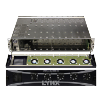
Rack Configuration
Assembly
If starting with an empty R FR 5018 rack frame please follow the following steps for
correct installation of the Series 5000 Card Modules
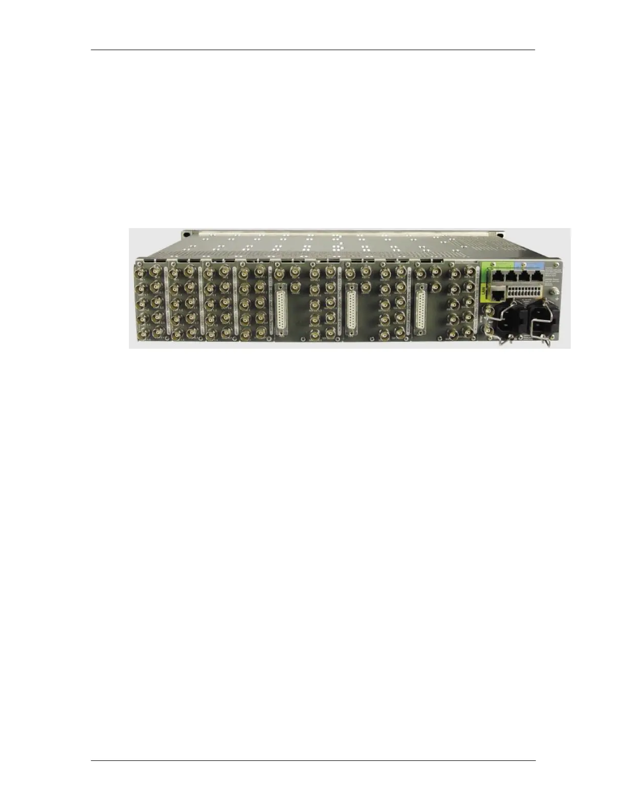
Rack Layout Considerations
If you have a variety of module types it’s a good idea to plan the order in which you install
the various CardModules. While a module can occupy any of the 10 available slots
provided, consideration can be given to the position of the modules in the rack to facilitate
external wiring. Below you can see an example layout.
Rear Connection Plates
The series 5000 CardModule is supplied with a connection plate and mounting screws.
This is fitted to the rear of the rack frame behind the module.
Installing Rear Connection Plates
Position the connection plate on the rear mounting rails and secure with the screws
provided. Do not fully tighten the screws initially. Test fit the module into the rack and
make sure the edge connector on the module is aligned correctly with the connection
plate. When alignment is correct, tighten the two screws. Remove and insert the module
a few times to check installation. If the module binds or sticks, or installation is in anyway
difficult then loosen the connection plate screws and check alignment. Repeat this
process for each module.
Redundant Power Supply
The basic RFR 5018 is supplied with the primary power supply installed. The redundant
supply (option) is installed next to the primary supply.
Remote Controller
Depending on your system design you may have the LYNX controller option available (R
CT 5023-G). Install the controller into the first module slot next to the power supply(s).
This is an extra slot reserved only for the controller cards. Please refer to
documentation supplied with the controller for the configuration and use of the LYNX
controller options.