Form # 46620 Issue 01/06
78
UNLOADING & ASSEMBLY
INSTALLATION:
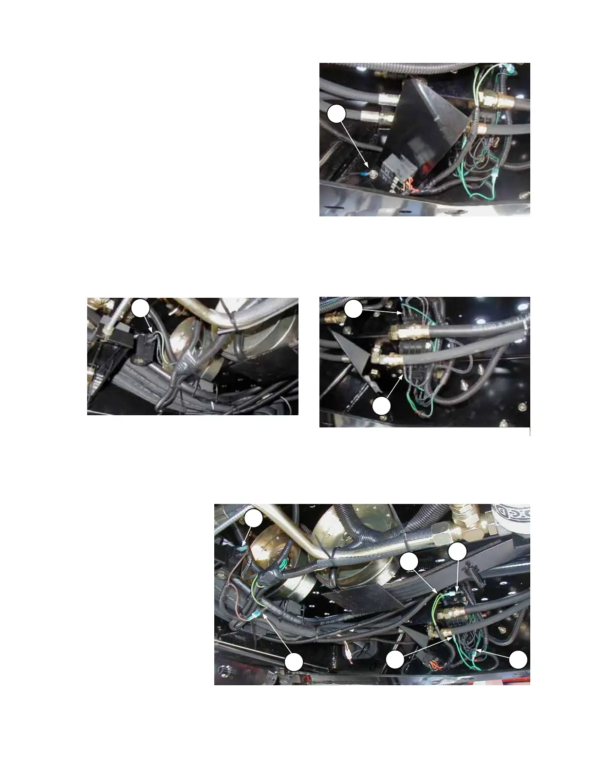
8. Install electrical harness (continued):
• Mount harness relay block onto front shield for
cylinder control valve. Use two #8 x ¾ inch truss
head screws and lock nuts.
• Plug the two relays into harness block.
• Attach kit harness ground wire to shield mounting
bolt at (J). IMPORTANT: Scrape paint off of both
sides of bracket and off frame in area surrounding
mounting bolt. Ground terminal, bracket and frame
must have metal-to-metal contact to ensure proper
ground.
• Route kit harness (as shown in bottom photo)
between cylinder control valve and header control
valve (located towards front/center of tractor).
Leave harness unsecured until connections are
made.
• Detach existing wire (K) 443 green from top solenoid (S2) of cylinder control valve.
• Detach existing wire (L) 444 green bottom solenoid (S3) of cylinder control valve.
• At header control valve, detach wire (M) 414 green from solenoid.
• Connect kit harness wire (N) marked 443 to top solenoid (S2) and connect tractor harness wire (K) 443
(removed above) to kit harness as shown.
• Connect kit harness wire (P) marked 444 to bottom solenoid (S3) and connect tractor harness wire (L) 444
(removed above) to kit
harness as shown.
• Connect kit harness wire
(Q) marked 414 to header
control valve solenoid and
connect tractor harness
wire (M) 414 (removed
above) to kit harness.
• Use plastic ties provided to
secure kit harness to
existing hoses/harnesses
to prevent contact with
moving parts.
J
MOUNT HARNESS BLOCK ON SHIELD &
ATTACH GROUND WIRE
K
L
DETACH EXISTING WIRES 443 & 444 FROM
S2 & S3 AT CYLINDER CONTROL VALVE
DETACH EXISTING WIRE 414 FROM
SOLENOID AT HEADER CONTROL VALVE
M
N
K
P
L
M
Q
MAKE HARNESS CONNECTIONS AND SECURE ROUTING