Form # 46584 Issue 11/06 Web Rev_01
144
ASSEMBLY
Radio Installation
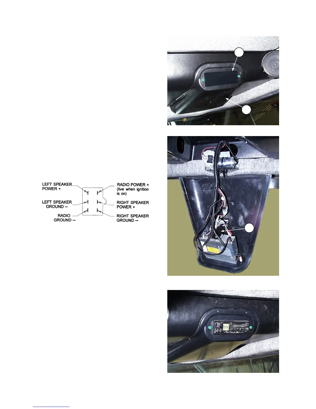
Provision has been made for easy installation of a
radio:
• Remove six screws around outer edge of panel
(A). Panel hangs on wiper motor with a plastic
tie. If it is desired to work at a bench, unplug
turn signal lights and slip tie off motor to release
panel.
• Remove decal (B) and remove radio cut-out
piece from panel (A) by cutting through four
tabs.
• Install radio in cut-out.
• Secure rear of radio body to support (F).
NOTE: For short body radio, bend support (F)
as required.
• A six-pin connector for the radio is included in
the wiring harness. In order to mate properly
with this connector, the radio must have a six-
pin connector (Packard #2977042) and have a
terminal arrangement as follows:
• Attach two additional wires in the wiring harness
to the radio:
Circuit 503, Red with 1/4" female blade
terminal. This is a live wire provided for
powering a radio clock/memory, if these exist
on your radio.
Circuit 315, Black ground wire attaches to radio
body.
• Plug cable from antenna into radio.
NOTE: An approved radio package is available
from Radio Engineering Industries (REI) of
Omaha, Nebraska.
A
B
RADIO CUT-OUT LOCATION
F
RADIO REAR SUPPORT
RADIO INSTALLED