Do you have a question about the Mackie 1620 and is the answer not in the manual?
Covers numbered safety instructions for apparatus usage and environment.
Warnings related to electric shock, moisture, and fire hazards.
Guidelines on safe noise exposure levels and hearing protection.
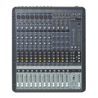
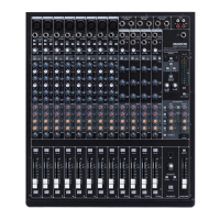
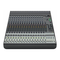
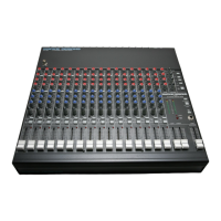
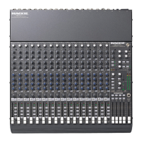
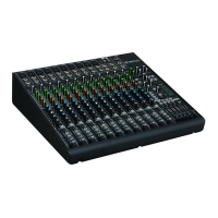
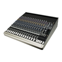
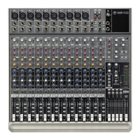
Describes the Onyx 1620 mixer's features and design.
Explains how to use the owner's manual effectively.
Steps to set mixer controls to zero before operation.
Essential steps for connecting inputs and outputs.
Procedure for setting input gain for optimal signal levels.
Basic instructions for achieving an initial mix.
Diagram illustrating a live sound and multitrack recording configuration.
Diagram showing a typical studio multitrack tracking setup.
Diagram illustrating a computer-based recording connection.
Diagram for recording with a FireWire interface to a laptop.
Details on channel strip layouts, MIC, HI-Z, and LINE inputs.
Explanation of Low-Cut filter, EQ bands, and bypass functions.
Description of GAIN control and 48V phantom power switch.
Features like EQ, AUX Sends, PAN, and MUTE/ALT 3-4.
Explanation of channel faders and signal level LEDs.
Operation of the SOLO switch and its modes.
Description of MAIN MIX fader and POWER LED indicator.
Choosing audio sources for control room and headphone outputs.
Routing selected sources to the main mix output.
Adjusting levels for control room and headphone outputs.
Connection point for stereo headphones.
Operation of SOLO mode and peak metering system.
Description of the RUDE SOLO indicator light.
How AUX sends and returns function for effects and monitors.
Level controls for AUX sends and pre/post fader routing.
Using the FX TO MON switch for monitor sends.
Using the internal or external talkback microphone.
Adjusting talkback volume and routing to outputs.
Outputs for monitoring and alternate mixes.
Main stereo outputs and tape recorder interface.
Connector for attaching a gooseneck lamp.
Location and function of the main power switch.
AC power inlet and external talkback mic connector.
XLR main outputs and signal level selection.
1/4" TRS jacks for auxiliary sends and returns.
Insert jacks for connecting external processors to channels.
Detailed explanation of how to use channel insert jacks.
Description of DB25 connectors for direct channel outputs.
Details on the optional FireWire I/O card for digital audio.
Steps for obtaining warranty service and repairs.
Guide to diagnosing and resolving problems like no power or bad sound.
Process for sending the mixer for service and repair.
Explanation of XLR connector pinouts for balanced signals.
Description of TS and RCA connectors for unbalanced signals.
Information on converting between balanced and unbalanced audio lines.
Usage of TRS jacks for send/return insert points.
Using mults and Y-cables for signal distribution.
Detailed pin configuration for DB25 recording outputs.
Comprehensive list of technical specifications for the mixer.
Dimensions, weight, and AC power requirements.
Information on optional accessories and indicator sensitivities.
Explanation of VU meters and channel level set LED.
| Channels | 16 |
|---|---|
| Direct Outputs | 8 |
| Type | Analog |
| Subgroups | 4 |
| Phantom Power | Yes |
| Mic Preamps | 8 |