Owner’s Manual
9
Owner’s Manual
This is the perfect setup for any venue where the audience is level with and above the stage. For example, a bowl, a shed
or a gym with bleachers.
The lef output from a mixer feeds the input of a Mackie DRM2A powered loudspeaker. The output of that Mackie DRM2A
feeds the input of the next Mackie DRM2A. This daisy-chained array is repeated once more to complete the tri-fecta.
Since three units are used, the array mode should be set to either 3-4 or 3-4 long and the subwoofer HPF set to o.
See page 6 for more information about the array mode and the choices available.
It is possible to reproduce this exact same hookup in stereo. Simply utilize the lef and right main outputs from the mixer
to feed the main inputs of the first DRM2A on each side of the stage and mirror the rest of the system as described above.
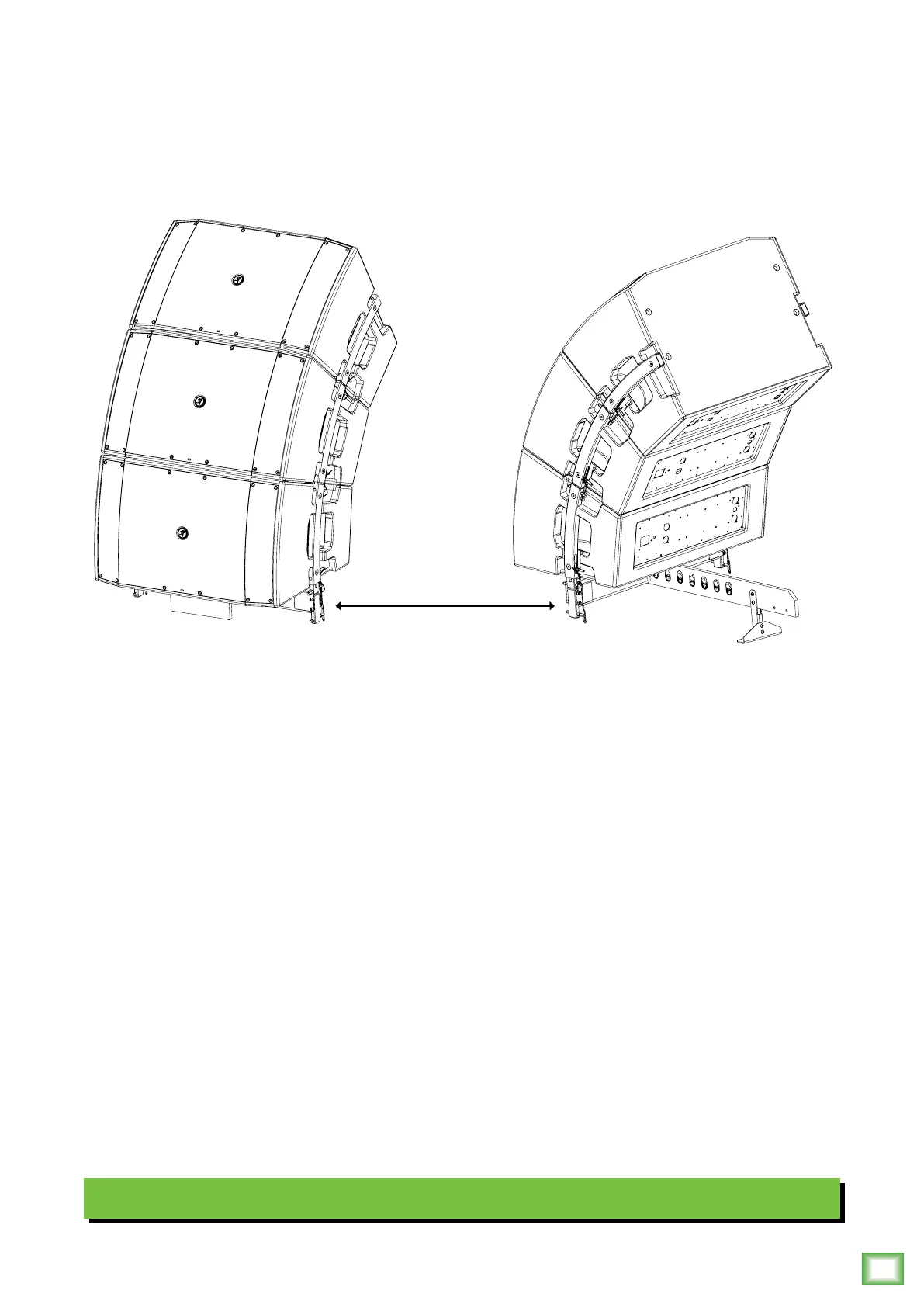
Another important aspect to keep in mind is the rigging setup of loudspeakers. In this diagram, the DRM2As are ground
stacked on the FB00 Flybar and the kickstand is included for additional support. This may be a full-range system
(as illustrated above) or add some DRM8S subwoofers to the system for extra thump. You could even mount the DRM2As
on top of the sub as shown on the next page. Refer to page 22 to view a table listing other configuration possibilities and
pages 24-26 for more information about rigging.
Note that the DRM2As AC power may be linked via the AC Thru. Refer to page 6 for details on daisy-chaining AC power.
Hookup Diagrams continued...
Ground-stacked with FB00 Flybar Accessory
FB100 Flybar